To change the view, you can use the zoom functions or use the corresponding combinations of mouse buttons and keys.
The following keyboard and mouse combinations can be used to manipulate the view:
All functions controlling the display are available in the View menu or in corresponding icons.
Redraw - F6 |
Quickly refreshes the 2D area.
Regenerate - REG |
Regenerates and redraws all 2D objects.
You can change the size of the view by using the following zoom functions:
By default, view change is animated. In command “CFG”, you can set animation properties or turn the animation off.
The Save View function enables you to save the current view for future use. To display a saved view, use the Restore View functions. You can save up to eight views. The Predefined Views toolbar makes it easy to switch between saved views. See also Saving Views.
Settings of 2D objects displaying are available in command “CFG”, in 2D section. It enables you to increase the number of segments used for drawing of 2D circles. When the number of segments is higher, circles will always appear smooth even when zoomed closely. A high number of segments may slow down drawing speed, especially on slow computers and extremely large 2D drawings.
Sets the aperture size of 2D cursor.
Displayed Cursor Coordinates - DCC |
Coordinates can be measured relative to a user-defined origin, or as DX, DY from the last point. Angle and radius from the last point are displayed automatically in most cases.
In 2D drawing you work with basic objects. These objects behave like individual entities when selected, and they can later be combined into blocks. The basic 2D objects are as follows:
For more information about creating blocks, see 2D Blocks.
File attributes can be defined when creating a new file (see Creating and Opening VariCAD 2D/3D Files ). This section describes the functions used to change 2D drawing parameters such as drawing units, format and scale. Attribute functions can be found in the Tools menu.
Change Units - CHU |
Change units in the current file by toggling between inches and millimeters. For example, an object defined to be 1” long will convert to 25.4 mm. Dimension text values do not change, nor do attributes of inserted mechanical parts. For example, Screw M10 will always have the same attributes, even if units are changed.
Drawing Format - FMT |
Changes the current drawing format. The format controls the view area, sheet border, and print attributes.
Sheet Borders Definitions - SBD |
You can define custom sheet border formats, modify existing formats, and define the method of drawing sheet borders.
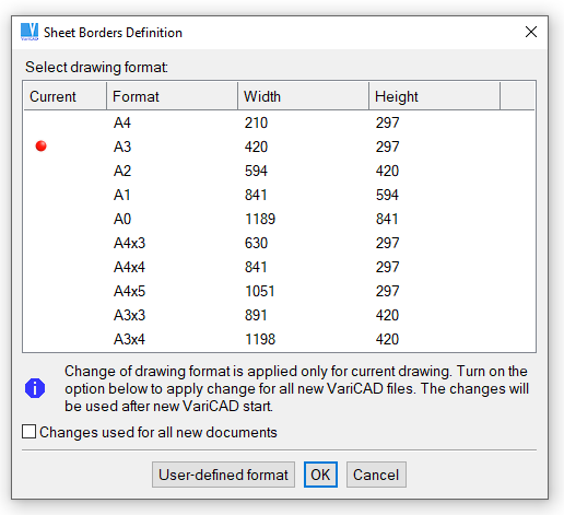
Formats window
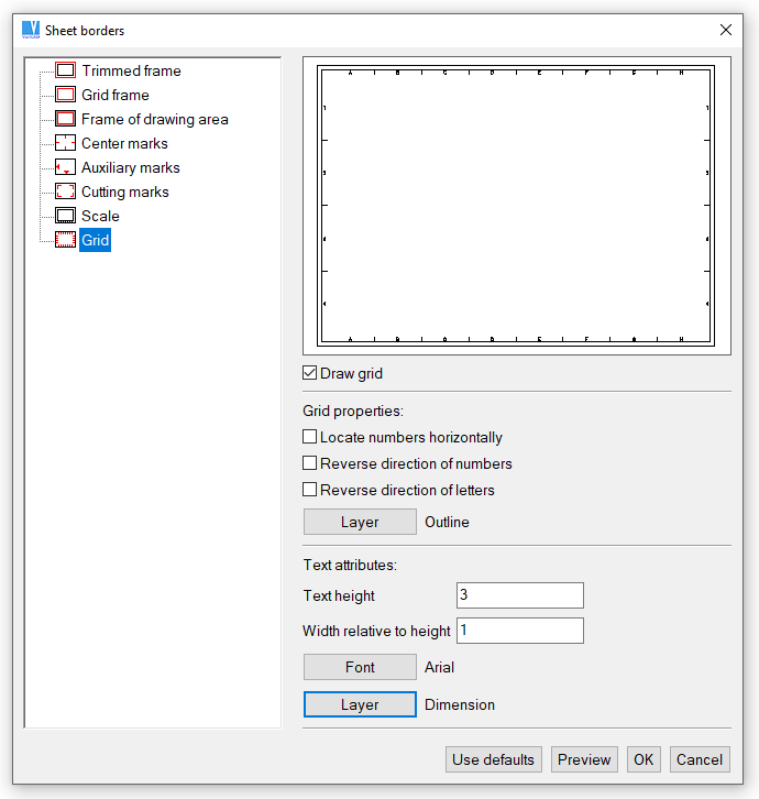
Sheet Border window
Sheet Border - BOR |
Creates a sheet border around the 2D drawing area. The lower left corner of border corresponds to the origin in global coordinates. Border width and length are determined by the drawing format. Border drawing method setting is defined in Units and Sheet Border.
System draws a rectangle around the current sheet border, regarding the current drawing scale. The rectangle is drawn in the same style as an auxiliary grid. This format border is not printed and cannot be detected, it is only displayed. Contrary to the format border in the drawing background, you can insert a border created in a configured style from detectable and printable 2D lines. Such a border is a part of the current 2D drawing.
You can turn on/off drawing of the background sheet border in the command “CFG” (system settings). If turned on, the background sheet border is always drawn - it is not a part of a 2D drawing.
Drawing scale only affects 2D annotation objects such as text, dimensions, symbols and arrows. The scale affects the proportions of these objects. For example, with a 1:2 scale, a 100-mm line will print as 50 mm long. Text 3 mm high will print as 3 mm high. Changing the scale does not affect dimensions.
Change Drawing Scale - SCH |
Changes the 2D drawing scale. The scale is defined when the file is created, and this function can be used to change the scale. All objects in the file remain unchanged. New annotation objects such as dimensions and text are created in different proportions. We recommend finalizing the drawing scale before starting to assign dimensions.
2D objects have the following attributes:
You can define up to 250 layers in each file. Each file contains one predefined layer named “0.” In 2D assembly, layers can be used to distinguish between separate details. For detail views or 3D view exports, layers should be used for distinguishing outlines, axes, dimensions, hatches etc.
Each layer is defined by name, color and line type. New objects are always created in the active layer. The active layer can be changed at any time, even during object creation. You can also change the current color or line type without changing the layer. For each object, its layer, color or line type can be changed at any time.
If objects from another file are inserted into the current file, objects from unknown layers are inserted into Layer 0.
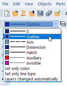
Setting the active layer
Layers - LAY |
Creates new layers, and edits or deletes existing layers. You cannot delete the active layer, a layer containing objects, or Layer 0. The command allows you to manage automatic layer switching.
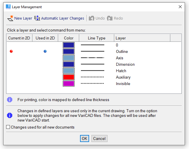
Layers window
Automatic layer switching can be set from the command CFG or LAY (see above). Automatic layer switching is useful for drawing 2D details. Layers are switched according to the executed function. Drawing functions like Line or Arc tools create objects automatically placed in Layer “outline.” Hatches are placed in “hatches;” dimensions are placed in “dimension.”
By default, automatic layer changing works with following layer order:
You can redefine the automatic layer switching. It is possible to select a single 2D drawing command or a group of 2D drawing commands and to assign a new layer automatically activated whenever the command is used.
Change Layer - MLA |
Changes the layer of selected objects to that of another object, or to a layer selected from the list of layers.
Highlight Layer - CHL |
Shows all objects on a specified layer, enabling you to check that the layer contains the correct objects.
For 2D objects, there are nine colors you can use. For 3D objects, there are 32 colors. Following dialog window contains list of colors available for 2D objects. The displayed color set is used for light background.
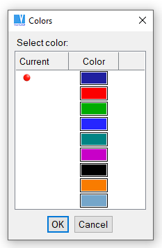
Line colors used in 2D drawing, for light background
For printing, line thickness is set according to color number. For color printers, you can map colors to other colors.
Change Color - MPE |
Changes the color of selected objects.
For 2D objects there are 7 line-types available. Following dialog window contains list of line styles available for line style selection.
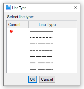
Line styles used in 2D drawing
Change Line Type - MLT |
Changes the line type of selected objects.
Blank 2D Objects - BLA, Ctrl + B |
Makes selected objects invisible. You can blank temporarily redundant objects, or objects that cannot be selected. Blanked objects are not printed, nor are they selected in selection windows.
Unblank 2D Objects - UBL, Ctrl + U |
Unblanks objects that were blanked, either in the entire drawing or in a specified area. You can also unblank individual objects, or all objects on a specified layer.
Work sets can be used to hold 2D objects. Work sets are useful when you want to delete or translate an entire set of objects. When inserting 2D objects from another file, you can place all new inserted objects into their own work set.
The following functions are used to manage work sets:
Add to Work Set - ATW |
Delete from Work Set - RFW |
Clear Work Set - CLW |
Deletes all objects from a work set
Highlight Work Set - CHW |
Helps you verify objects in the work set
VariCAD uses two types of coordinate systems. The absolute coordinate system has its origin at the lower left corner of the drawing area. The user-defined coordinate system is, by default, identical to the absolute system until a new origin is defined. The user-defined coordinate system is unique for each file. When 2D coordinates are used, they are always relative to user-defined origin.
User Origin - UCO |
Locates the user-defined origin or resets to the absolute origin.
More convenient method to change or reset the user-defined origin is to use Increment Cursor Mode and select the change from dialog panel.
The following aids are available to help you while creating 2D objects:
Ortho mode or increment cursor movement is displayed at right end of status bar. Also, corresponding icons in tool-bar are checked.
The orthogonal grid provides better drawing orientation and enables snapping to grid points. The grid is displayed in two levels of brightness. When the grid density is too high to display, the grid is automatically turned off. Snap distances can be smaller than the grid spacing.
The grid can be especially useful when translating entire sections of a 2D drawing or inserting 3D view exports. Grid snapping is available even when the grid is not displayed. Entered values are rounded to the nearest multiple of the snap distance. If you want to use the same grid settings in new documents save the current settings as default.
Grid – GRI, Ctrl + G |
Sets the grid spacing or turns the grid on or off.
Construction lines are “auxiliary” or temporary lines, independent of any other objects. You can create individual constructions lines or a mesh of them. Objects or other construction lines can be placed at the intersection points of other constructions lines – either intersection between two construction lines, or intersection between a construction line and a line, arc or NURBS curve.
Construction lines can be created as vertical, horizontal or angular. You can predefine two angles for angular lines. If you create a construction line or if you delete one or multiple lines, the step can be undone or redone again – similarly, as for any other 2D or 3D object.
Construction line functions are available from the Construction Lines toolbar, and from the Objects / Drawing Aids menu.
You can create construction lines as:
You can delete all construction lines, delete a selected line, or delete all lines by type (all horizontal, all vertical or all angular).
Apart of creation of individual lines or group of lines, you can create multiple construction lines – as the most convenient method.
Create Multiple Construction Lines - CCL |
This function creates one or multiple construction lines of all types – horizontal, vertical or angular.
Following options are available:
| Create Horizontal/Vertical Construction Lines – select a location and then direction the new construction line (lines) will be created at. The line or lines are created according to current selections – at a distance from the selected location, at a distance from the previous line or they are dragged by cursor |
| Create Angular Construction Lines – under predefined first angle, similarly as horizontal/vertical lines |
| Create Angular Construction Lines – under predefined second angle, similarly as horizontal/vertical lines |
| Drag Construction Line by Cursor – if this option selected, a new construction line is dragged by cursor until you select a location. By default, increment mode of dragging is used – for instance, the new line is dragged in increments of 1 millimeter. Distance from location is displayed near the cursor. If this option is turned off, the distance of a new construction line is defined by keyboard input or measurement. |
| Set Dragging Increment or Angles – sets increment of dragging, or predefined first and second angle of angular construction lines. |
| Measure Distance from Selected Point |
| Measure Distance as Offset from Previous Line |
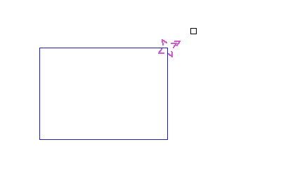
Selecting a direction of a new construction line
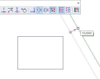
A construction line dragged by cursor, according to the previous selection

Construction Lines toolbar
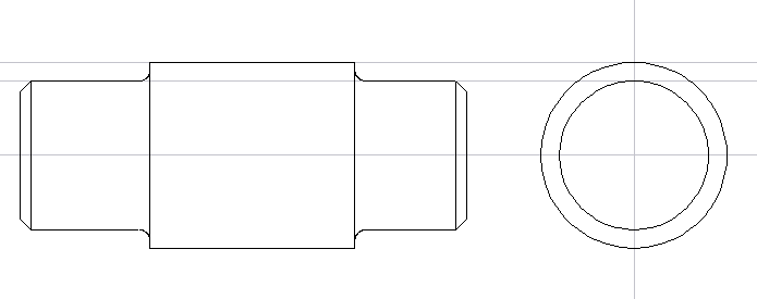
Example of construction lines used to create a side view
Temporary construction lines (leading lines) are automatically created at the last defined location and in these situations:
By default, these temporary construction lines are active in 2D drawing in 3D (in sketching). You can stick cursor at these construction lines and easily follow horizontal or vertical direction. In 3D sketching, you may not recognize directions of X or Y axis well, because of view rotation.
Transient construction line or lines are temporarily displayed, if X or Y cursor coordinate approaches:
Transient lines disappear, if cursor moves away from them more than defined distance. On the other side, you can follow a transient line by cursor movement until you reach an intersection of the transient line and a 2D object.
To turn on or off temporary or transient construction lines for sketching or 2D mode, run command “CFG”, or select Ortho Modes, Leading Lines
When not in Increment mode, the cursor moves smoothly and defined locations are based on display resolution. When using Increment mode, cursor locations are rounded to the nearest multiple of the increment distance. The square or arrow cursor movements are still smooth; only the resulting locations are rounded. Crosshair cursor movements “jump” in the defined steps. Increment mode is indicated in the Status Bar. Increment mode is especially useful when used in conjunction with a user-defined origin.
Increment Cursor Mode - STP, F9 |
Turns Increment mode on or off, or sets the XY increments of cursor movement. This command also allows you to set or reset 2D coordinate origin.
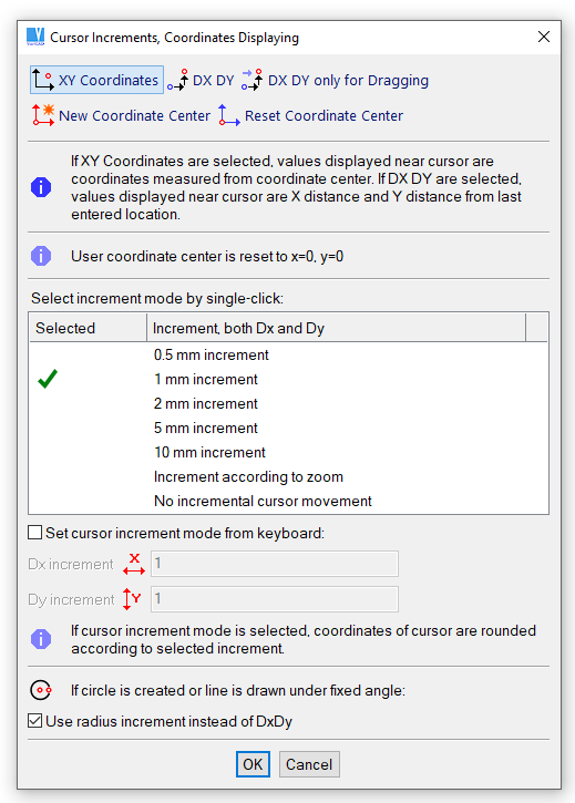
Setting cursor increments or coordinates origin
Ortho mode is an obsolete method. It is available as a legacy option. We recommend to work with temporary and transient construction lines rather than with Ortho mode. Besides, Ortho mode may be inconvenient in stretching, where you may have drawing plane displayed under various view angle.
In Ortho mode, created lines are always horizontal or vertical, according to current position of cursor. You can use Alternating Ortho mode, in which lines alternate between horizontal and vertical, regardless of cursor position. Ortho mode is indicated in the Status bar. Also, a corresponding icon in tool-bar is checked.
Ortho Modes, Leading Lines |
This command sets Ortho mode, turns off Ortho mode or configures temporary construction lines (leading lines).
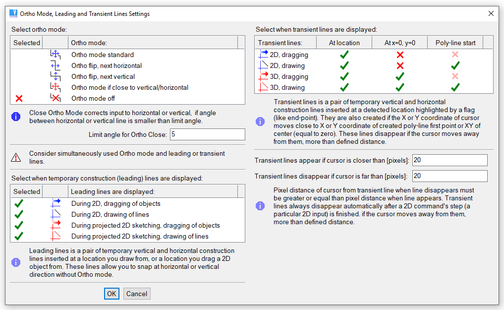
Ortho modes and leading lines settings.
Following commands manage various Ortho modes individually:
Ortho On - F11 |
Turns on Ortho mode.
Ortho Alternating H/V |
Turns on Ortho mode, alternating horizontal and vertical lines. The first line is horizontal.
Ortho Alternating V/H |
Turns on Ortho mode, alternating horizontal and vertical lines. The first line is vertical.
Ortho if Close to Vertical/Horizontal |
Ortho mode is used, if the angle of the current cursor location measured from the last input is close to horizontal or vertical direction. The angular limit can be set.
Set Close Angle for Ortho |
Sets the angular limit for the mode described above.
Ortho Modes – Shift + F11 |
Opens pop-up menu with all Ortho mode possibilities.
Ortho Off |
Turns off Ortho mode.

|
|
|