This section describes how you can change the shape of selected 2D objects and text. For information on how to select objects, see Selecting 2D Objects.
You can select a command, and then select objects to be edited. Or, you can select objects first and then select a command. Also, you can select an object or objects, then right-click an empty area and select a command from pop-up menu.
Delete 2D Objects – DOB, Ctrl + D |
Deletes one or multiple selected 2D objects.
Trim - TBO |
Removes sections of lines, splines or arcs that lie on one side of a trimming curve. You can also define a temporary trimming line by defining two points.
Remove Segment - RSG |
Removes a segment from an arc, spline or line. The removed segment is defined by two points.
Extend - EBO |
Extends lines or arcs to a defined curve. You can also define a temporary extension line by selecting two points.
Break Line - BLN |
Creates break marks on a selected line, by selecting the location of each break mark.
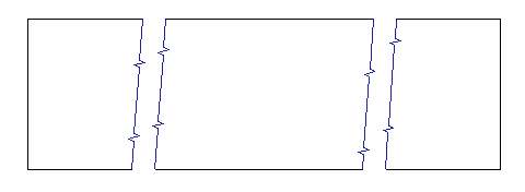
Example of break lines
Circle from Arc - CEC |
Creates a full circle from a selected arc.
Edit Spline - ESP |
Edits the selected spline. Select one of the spline definition points and drag it to a new location. While dragging, the spline shape updates dynamically. Press Enter or right-click to finish editing.
Change Line Length - CHLL |
Changes length of a selected line or performs stretching.
Change Arc Radius - CHAR |
Changes radius of a selected arc or a circle. If the arc is created as a rounded corner, VariCAD changes the fillet radius and preserves the filleting. You can select multiple lines, multiple arcs or multiple 2D rounded corners. Change is performed at one step for all selected objects.
Each of these functions can be applied to line, arc or NURBS segments. You can select both segments at once by selecting the intersection snap point, indicated by a V-shaped symbol at the cursor. If segments are selected separately, you can choose to apply the function to the first, second, or both segments. If any segments will be trimmed as a result of the function, select the segment on the non-trimmed portion.
Instead of selecting a particular command (for instance, by clicking a corresponding icon), you can press and hold Shift key and move cursor over corners or intersections of 2D objects. Whenever a V-shaped symbol appears, you can right-click and then select corner, chamfering or filleting from menu.
Some situations do not allow all three possibilities. If you already selected a function (like filleting), you may continue to fillet corners after finishing each step, until you select another command or interrupt by pressing ESC key.
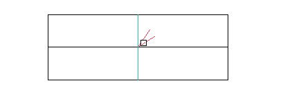
Selecting an intersection to be rounded
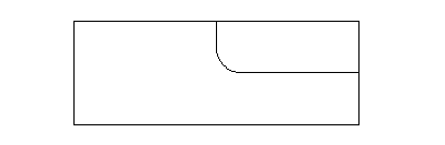
Result of rounding
Corner - CCO |
Creates a sharp corner at the intersection of selected segments. Segments will be trimmed or extended to create the corner, so select the segment on the non-trimmed portion.
Chamfer 2D Corner- CHM, Ctrl + R |
Creates an angled chamfer between two lines. You can define the chamfer by distance along each segment, or by distance and angle for one segment. You can choose whether to trim or extend segments.
Fillet 2D Corner – RND, Ctrl + F |
Rounds the corner between lines or arcs. When applying a fillet to two arcs, you can choose a convex or concave result. You can also choose whether to trim or extend segments.
Explode - EXP |
Explodes selected 2D object into their basic elements. Objects are exploded according to their type as follows:
Divide by Point - BPO |
Divides a line, spline or arc at the selected location, creating two separate objects.
Divide by Curve - BBO |
Divides a line, spline or arc by a specified curve, creating two separate objects. You can define a temporary curve by selecting two points.
Edit Text - ETX |
Modifies the selected text. The text lines appear in the editing window where they can be edited.
Text Attributes - TAC |
Changes attributes of the selected text. Before selecting text to change, define the new attributes and whether the text parameters, font or insertion point will be changed.
Align Text - JTX |
Moves text lines horizontally, aligned to a center point or to another selected point.
Text Width - TWD |
Changes the width of the selected text width. The new text width is determined as ratio of two distances you defined with the cursor.
Move Text Vertically - MTI |
Moves text lines vertically. The move distance is a factor of line spacing, and you must enter the number of lines to move. Text can be moved after text is deleted, or in order to insert text between lines.
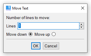
Move Text window
Explode Font into Segments - BTF |
Explodes 2D text letters into line segments. In older versions, exploded font contours were used for creation of 3D texts. Now, 3D text objects can be created by commands related to font extrusions – see 3D text

|
|
|