The 3D display provides the following features:
You can use the following standard methods to change your view dynamically:
Other methods are also available – they are usually provided to keep interface compatibility with older versions of VariCAD:
For dynamic view rotation, zoom or pan all keys and/or mouse buttons must be held simultaneously, of course.
Dynamic view changes can be set in command “CFG”.
If view is not changed dynamically by cursor movement or mouse wheel rotation, the change is animated. For instance – if you select a front view and the current view is under a random angle, the view is not redrawn immediately. Angle of view is changed within a few tenths of second. This gives you better impression of the change.
VariCAD permanently checks time of redrawing. If you have slow graphics and if you want to redraw a large amount of 3D data, animation is automatically turned off. Animation of view changes can be managed in command “CFG”.
You can use a predefined angle of 3D view. Predefined view is created from front view by rotation around X, Y and Z axes of display. It can be set in command “CFG”. By default, the predefined view is used whenever a new file is created.
Predefined View - PRV |
This command sets the view according to predefined angles.
You can use the arrow keys to rotate the view around a specific axis. Press Shift, Ctrl, or both, and then press the following:
You can use the keys in combination to change the view angle.
Left View - VLE |
Right View - VRI |
Front View - VFR |
Back View - VBA |
Top View - VTO |
Bottom View - VBO |
Isometric View 1 |
Isometric View 2 |
View to Plane - RNP |
Sets the view perpendicular to a selected plane. This tool is useful especially when creating a 2D view export.
Rotate View Around X 90 Degrees - X90 |
Rotate View Around X 180 Degrees - X180 |
Rotate View Around X 270 Degrees - X270 |
Rotates the view by the specified angle around the global X axis (horizontal axis)
Rotate View Around Y 90 Degrees - Y90 |
Rotate View Around Y 180 Degrees - Y180 |
Rotate View Around Y 270 Degrees - Y270 |
Rotates the view by the specified angle around the global Y axis (vertical axis)
Rotate View Around Z 90 Degrees - Z90 |
Rotate View Around Z 180 Degrees - Z180 |
Rotate View Around Z 270 Degrees - Z270 |
Rotates the view by the specified angle around the global Z axis (perpendicular to display plane)
Undo View - ZPR |
Redo View - ZRD |
Zoom Window - ZWI |
Defines the zoom by specifying opposite display corners
Zoom All - ZALL |
Adjusts the view to display all visible objects
You can save up to eight views that contain rotation, zoom and pan settings. The Predefined Tools toolbar enables you to easily restore these saved views.
| Save View - click this icon and select the number of the saved view. |
The other icons on this toolbar restore the numbered views. Your views are saved with the file.
Both the 2D and 3D components of a file can each contain eight saved views.
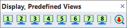
Predefined Views toolbar
Shade/Wireframe Entire Display - SHW |
Switches the display from shaded to wireframe or vice versa.
3D Shading and Edges Settings - 3DS |
Enables you to change how 3D objects are displayed. You can define:
Colors and Wires of Solids - SCO |
This function defines:
You may also select different colors for entire groups of objects. Thus, the objects are distinguished easily from the rest. This option overrides objects' own colors, if turned on. Turned off, the objects are displayed again in their own colors.
You may select a distinct color for:
These options are turned off, if a color is defined by solid’s material.
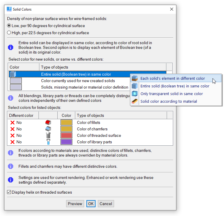
Solid display settings window
Whenever you rotate 3D view, the view rotates around a defined point. You have several methods to redefine the view rotation center. The best option is to right-click an empty area and to select the change from pop-up menu.
Auto View Rotation Center - VCN |
Sets the view rotation center to the center of geometry of all visible solids.
Define View Rotation Center - VCNI |
Sets the view rotation center to a specified location, selected by cursor.
View Rotation Center to Display Center |
Sets the view rotation center to center of viewport. This option is especially recommended for enhanced rendering.
Enhanced Rendering - SRD |
Renders 3D objects more precisely. Smoothly rendered images are realistic and can be used in product presentation materials such as brochures, printed PDF files, folders etc. Once selected, enhanced rendering persists until any 3D edit function is called. It means that you can use all functions working with display, like standard views, view rotation etc. and enhanced rendering is still present. Display settings are the same as for standard mode; however, set values are different for each display mode.
Enhanced rendering is recommended if you want to create a bitmap output of images, or for printing of 3D display.
For enhanced rendering, you can set the following attributes:
For surface shading, you can set the following attributes:
It is recommended to combine enhanced rendering with selection of a proper color palette. All values can be changed by cursor movement, effect is seen immediately and values can be reset whenever.
The settings are different for shaded solids and for transparent solids.
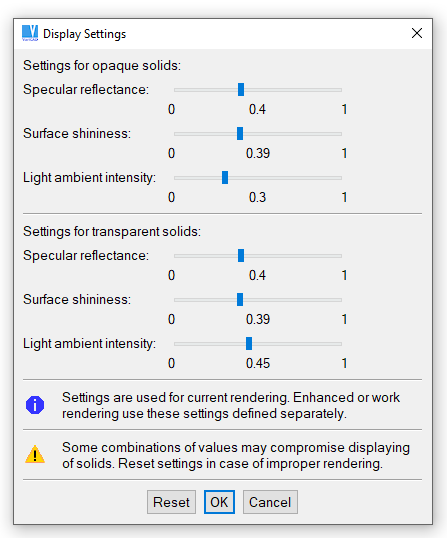
Shading surface settings window
During start, VariCAD detects supported OpenGL version. If available, OpenGL 4.3 or at least 4.0 is used. For older hardware or insufficient OpenGL support, VariCAD works with OpenGL 1.1. In such situation, some features may be limited.
OpenGL 4.0 and higher allows you to fully exploit power of graphic adapter (card). Rendering time of large 3D data is significantly shorter than under old OpenGL 1.1.
If necessary, you may redefine which OpenGL version is used – although we recommend to let the decision at VariCAD system. To change the OpenGL version, run command “CFG” and then select “OpenGL Version and Initialization Settings”.
To change functionality of OpenGL, you may run command “CFG” and select “Performance, 3D Graphics, OpenGL”. For OpenGL 4.0 and higher, you may select:
If hardware does not support anti-aliasing sufficiently, VariCAD automatically turns it off. You may override such blocking.
Example of the aliased display method
Example of the anti-aliased display method
For old OpenGL 1.1, you may select:
Again, we do not recommend to change the behavior, if there are no problems detected. Changing these settings may be useful only if hardware or display driver performance is erroneous and you are looking for a method how to circumvent problems.
VariCAD is an OpenGL application. It means that for displaying of 3D objects, VariCAD uses the OpenGL functionalities. The OpenGL standard is widely supported by hardware manufacturers.
We recommend to work with hardware accelerated OpenGL. It means that final displaying of 3D objects is calculated directly in the graphic adapter (or, in other words, in the graphic card). Even in case the computer is fast enough, displaying is slower if calculated by CPU. Moreover, software emulation of OpenGL may not be always fully compatible with the standard. This may be a problem especially for older hardware.
If you are working under Windows operating system and if your computer has a graphic adapter like NVIDIA or ATI, OpenGL is likely hardware accelerated. Only some cheap solutions working with graphic adapters integrated on the board may be slow.
Under Linux operating systems, OpenGL may not be fully supported. To solve this problem, we recommend you the following:
Test of Hardware - HWTEST |
This function is useful if you want to compare performance of different VariCAD settings or different hardware, like graphic adapters, main boards, processors etc.
The best option is to run the test after start of VariCAD, with no open files. VariCAD creates its own benchmark file. Then, hardware performance is measured. Results are displayed and can be saved into a text file. For the benchmark file, results are comparable. Optionally, you may run the test with any currently open file.
The test measures and displays:
Results depend also at other hardware components.

|

|

|