When locating a solid in 3D space, it is placed by its insertion point. The insertion point of each solid is defined during the solid creation. When solids are joined together, the default insertion point becomes the point of the object to which the other object is added (the root solid). When inserting multiple objects, the insertion point of the first selected object is used. You can redefine the insertion point location at any time.
Each basic element has its own axes. These axes are displayed when the object is inserted, or whenever its position changes. The origin of a solid’s axes is at its insertion point. These axes can be used for translation and rotation for the attached solids, as well as for other solids.
The global 3D X, Y, and Z axes are always displayed at the lower left corner of the 3D area. These axes indicate only the axis directions; the origin may be elsewhere. When first inserting a solid, the solid axes are identical to the global axes, until the solid position is changed.
Translate, Rotate, Copy Solids - STC, Ctrl + Q |
First select the objects to be transformed or copied. Then define their new location. You can select entire objects as well as their separate components such as holes. If components are selected, some parts may not regenerate after transformation. For example, if you move a hole outside its object, the hole cannot be generated. In this case you will receive a warning message. Methods of insertion, translation, copying, etc. can be selected from the 3D Location toolbar. This temporary toolbar appears whenever solids are inserted or transformed. There are also case-sensitive hotkeys for most options.
Some functions require a predefined vector or rotation axis. You can define these by the following methods:
Whenever 3D objects are transformed or inserted, their axes are displayed at the location of the object’s insertion point. Although you can use any transformation methods clicking icons in the panel (see the next sections), the most comfortable method is to use the axes directly:
Example of solid’s transformation. Solid is translated along its Z axis.
The color of the axes depends on current color palette. By default, for a dark background the X axis is red, Y axis white and Z axis green. For a light background, X axis is red, Y axis blue and Z axis green.
Moves solids according to a specified axis and distance.
| Icon | Key | Use |
| x | Moves along the solid’s own X axis | |
| y | Moves along the solid’s own Y axis | |
| z | Moves along the solid’s own Z axis | |
| t | Defines a vector along which to move | |
| T | Moves along the predefined vector |
First, define the axis the solid is dragged along. If you want to move the solid along own X, Y, or Z axis, then simply click the inner part of the corresponding solid axis.
Then, define a location, which is projected to a dragging vector. The solid insertion point is translated along the vector to the projected location. Move the cursor to translate objects dynamically. Press Enter or left-click to finish translation. You can drag objects while moving the cursor or the objects are moved only if you detect a new location. See 3D Locations Settings.
If you press and hold left mouse button during dragging, automatic detection is turned off. This is convenient if you use dragging in increments.
| Icon | Key | Use |
| N/A | Moves dynamically along the solid’s own X axis | |
| N/A | Moves dynamically along the solid’s own Y axis | |
| N/A | Moves dynamically along the solid’s own Z axis | |
| N/A | Defines a vector along which to move dynamically | |
| N/A | Moves dynamically along the predefined vector |
Rotates solids around a defined rotation axis, by a specified angle.
| Icon | Key | Use |
| u | Rotates along the solid’s own X axis | |
| v | Rotates along the solid’s own Y axis | |
| w | Rotates along the solid’s own Z axis | |
| r | Defines an axis around which to rotate | |
| R | Rotates around the predefined axis |
First, define a rotation axis. If you need to rotate only around solid’s own axis, then click the small circle at the inner part of the axis.
Then, define a reference point. Objects are rotated by movement of the reference point. As a reference point, you can use a tip of one of the two remaining axes.
Press Enter or left-click to finish rotating. You can drag objects simply moving the cursor or the objects are moved only if you detect a new location. See 3D Locations Settings.
| Icon | Key | Use |
| N/A | Rotates dynamically along the solid’s own X axis | |
| N/A | Rotates dynamically along the solid’s own Y axis | |
| N/A | Rotates dynamically along the solid’s own Z axis | |
| N/A | Defines an axis around which to dynamically rotate | |
| N/A | Rotates dynamically around the predefined axis |
You can drag objects (move or rotate) incrementally. If you move the cursor over edges or edge endpoints, the location is always defined by projection of a detected point to the dragging vector (or similarly for rotation). However, if you turn on the incremental dragging and if the cursor is not crossing any detection points, the movement distance (or rotation angle) from the initial location is rounded according to currently used dragging increment. You can check the distance near cursor or in status-bar.
To set dragging increments or to turn them off, right-click during dragging and select values from menu.
| This option also allows you to turn on or off the incremental dragging and to set values of increments for translation and rotation. |
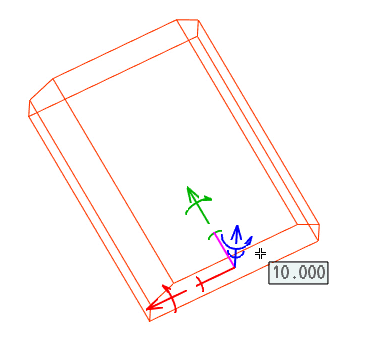
Example of solid dragging, distance from start of dragging is displayed near cursor. The solid is dragged along its Z axis.
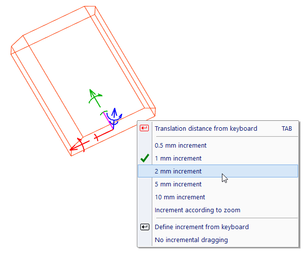
Example of solid dragging, after right-click. Pop-up menu offers increment options.
VariCAD allows you to perform additional rotation of transformed objects around an axis. You can select rotation from a panel containing transformation commands or from a pop-up menu after clicking the inner part of the translation axis. Then enter a rotation angle and the objects are rotated around the corresponding axis. Axes remain in the same position.
Additional rotation can be conveniently combined with geometrical constraints and parameters.
| Icon | Key | Use |
| N/A | Additional rotation around own X axis | |
| N/A | Additional rotation around own Y axis | |
| N/A | Additional rotation around own Z axis |
These functions can be used to reorient a solid by changing the direction of its axes.
| Icon | Key | Use |
| N/A | Sets solid X axis direction along defined vector | |
| N/A | Sets solid X axis direction along previously defined vector | |
| N/A | Sets solid Y axis direction along defined vector | |
| N/A | Sets solid Y axis direction along previously defined vector | |
| N/A | Sets solid Z axis direction along defined vector | |
| N/A | Sets solid Z axis direction along previously defined vector | |
| N/A | Sets all solid axis directions along all axes of another entire solid | |
| N/A | Sets all solid axis directions along all axes of another part of solid |
These functions enable you to direct a selected axis according to a surface and simultaneously, locate at a surface. Surface location is the location detected by cursor movement, under the cursor at a solid. It can be combined with location at an edge or edge endpoints.
For example, you can position a drilling tool, when a hole is created. The tool’s X axis must be directed against a normal of detected surface. The tool is automatically located at a surface. As you move cursor, the tool remain stuck under the cursor at a surface.
These features are accessible from pop-up menu, if you right-click the inner part of corresponding solid axis.
| Icon | Key | Use |
| N/A | X Axis against Normal and Locate at Patch | |
| N/A | X Axis along Normal and Locate at Patch | |
| N/A | Y Axis against Normal and Locate at Patch | |
| N/A | Y Axis along Normal and Locate at Patch | |
| N/A | Z Axis against Normal and Locate at Patch | |
| N/A | Z Axis along Normal and Locate at Patch |
These functions enable you to position solids relative to a selected plane. The solid axes can be directed along or against the plane normal. See also Selecting Planes.
| Icon | Key | Use |
| N/A | Sets X axis against plane normal | |
| N/A | Sets X axis along plane normal | |
| N/A | Sets Y axis against plane normal | |
| N/A | Sets Y axis along plane normal | |
| N/A | Sets Z axis against plane normal | |
| N/A | Sets Z axis along plane normal | |
| N/A | Sets normal of any selected solid’s plane along another plane normal | |
| N/A | Sets normal of any selected solid’s plane against another plane normal |
Whenever you want to insert a new solid, the solid axes are at the last inserted location by default. Or, if no objects were inserted yet, the axes are at the coordinate center. Often, the axes may be outside of the current zoom.
Zoom in on Objects' Transformation Axes |
This command opens a pop-up menu with following options:
| Icon | Key | Use |
| N/A | Zoom in on Objects' Transformation Axes | |
| N/A | Objects' Transformation Axes to View Center | |
| N/A | Undo View | |
| N/A | Redo View |
Transforming object location, you may right-click other objects outside the transformed group. Right-click an edge opens a pop-up menu with locate modes. This way you may comfortably locate object at an end point, center point, circle center etc.
Solid transformation, right-click an edge of another solid
Right-click the transformed solid, you open a pop-up with options related to transformation, like new insertion point etc. Previous option is available for multiple objects types (not only solids, but also axes locations). This option is available only for solid transformation.
Solid transformation, right-click an edge of transformed solid
After the final position of transformed or inserted objects is defined, you may optionally perform a Boolean operation. Objects can be added to or cut from a selected root solid.
You may also select repeated Boolean operations. In such a case, the operation is performed each time you press Enter or click the corresponding icon (the Insert icon). The object is used as a Boolean operation tool, the operation is performed and then the copy of the original object is transformed again. Using this method, you may repeatedly insert and add solids to one selected root solid. You may also add multiple solids to one root solid at a time.
You can also define geometric constraints. Constraints are defined after a Boolean operation. For more information about the geometric constraints, see Geometric Constraints. Available options are:
Additional Boolean Operation after Location |
| Insert and add to a selected solid. |
| Insert and cut from a selected solid. |
| Insert and add to a selected solid repeatedly. |
| Insert and cut from a selected solid repeatedly. |
| Stop the repeated Boolean operations. |
Define or Edit Constraints after Location |
| Insert and add to a selected solid. |
| Insert and cut from a selected solid. |
| Insert and define constraints of entire solids. |
You can redefine a solid insertion point at any time. If you are transforming multiple solids, the insertion point of the first selected solid is used, but you can choose to use another insertion point. There are also options for displaying solid axes. See also Solid Object Coordinate System.
| Icon | Key | Use |
| n | Defines new insertion point | |
| N | Defines solid whose insertion point will be used |
Transformed solids are inserted into their final position by pressing Enter or right-clicking. You can also choose to copy instead of insert. In this case, you must insert the transformed objects first. After insertion, the objects are copied and you can continue inserting. You cannot insert a copy into the position of the original object.
When an object is copied, its attributes are copied as well. Therefore, we recommend assigning attributes before copying. You can also create identical (linked) copies that share future edits (see Identical Copies of Solids.
| Icon | Key | Use |
| Enter | Insert - inserts object into their final position | |
| N/A | Undo - goes one step back, undoes previous transformation | |
| + | Copy | |
| - | Cancel Copy - turns off copying | |
| N/A | Copy, creates identical copies |
When copying solids, you can choose to create identical (linked) copies. This means that if any member of the copy group is changed, the change is automatically implemented on all group members. When one object in the group is selected, all identical copies are highlighted. Identical copies are also created when inserting a part into an assembly.
When copying members of a group of identical copies to another location, newly created objects are members of identical copies only if identical copying is turned on. In case of plain copying, these objects do not belong to a group of identical copies.
Break Identical Copy Link - RSI |
Enables you to select objects to be removed from the group of identical copies or from group of solids inserted from a part (assembly-part connection). This breaks the link between the objects.
Break Identical Copy Group - RIC |
Breaks connection between all solids and a corresponding identical copy group.
Add Solids to Identical Copies – ASI |
This command creates an identical copy group from selected solids. First, select a solid – it will replace entire group of solids selected in next step. Such method may be useful if you originally copied solids as plain copies and later, it is necessary to have identical copies instead of plain copies.
Permanent Change of Imported Solid Axes - CHAX |
Solid axes are located at a solid according to solid creation method. Although you can define offset of axes, system still remembers their default position and you can reset the user-defined offset. For more information, related to solid axes see Solid Insertion Point.
If solids are combined into a Boolean tree, entire solid inherits the axes from so called root solid.
If a solid is imported from STEP, the axes are determined automatically and their position at a solid and their rotation relative to a solid may not be convenient. This command allows you to change axes of imported solid permanently – not only to define an offset, but also to rotate them.
Using snap points and significant locations can be used when inserting and transforming solids, as well as in other functions such as measuring and checking. You can use either toolbar icons or keyboard keys. The cursor automatically detects solid edges and curves. If the cursor approaches a snap point, a symbol appears next to the cursor. Clicking when you see this symbol selects the point. The following letters indicate snap points:
To snap at any location related to solid edge, you may use the same method as for solid transformation – see Additional Options for Right-Click Objects during Transformation.
To snap to an endpoint E, midpoint M, or arc/curve center of gravity point C, press the corresponding key when the edge is highlighted. To use the toolbar icon, click the icon first and then click the edge or object. If you click on an edge when no snap point is indicated, the location is defined at the point on the edge nearest to the cursor.
If you select any specific location mode clicking icon in select toolbar, then the only selected mode is performed. For instance, if you select location of midpoint of edge, whenever you approach any edge, its midpoint is highlighted. The point can be detected clicking left mouse button wherever over corresponding edge. Predefined location mode persists until any selection is performed, or until any other mode is selected or until you click the same icon again.
There is a difference between the center of gravity of a curve and the center of an arc. The arc center is the point from which all arc’s points are at same distance. Only for a full circle are the center and center of gravity identical.
| Icon | Key | Use |
| m | Midpoint of edge | |
| e | Edge endpoint | |
| 2 | Circle or arc center | |
| c | Center of gravity of edge | |
| N/A | Snap to nearest point on selected edge | |
| k | X, Y, Z coordinates | |
| d | Delta X, delta Y, delta Z from a specified point | |
| g | Between two points, at a defined distance from the first point | |
| b | Halfway between two defined points | |
| p | Solid (element) insertion point | |
| q | Entire solid insertion point | |
| N/A | Intersection of a rotation surface axis and a plane | |
| N/A | Intersection of a line and a plane |
The cursor automatically detects planes. If plane selection is required and the cursor moves over a plane, all plane boundaries are highlighted. The plane is selected by clicking when the plane is highlighted. It is possible to have plane boundaries common to more than one plane and select plane of wire-framed object. In such cases, approach the plane boundary from inside the plane, proceeding toward the boundary.
You can set 3D locations settings from command “CFG”. The following location options are available:
Mirror - MIRR3 |
The mirror plane must be defined first, by one of the following methods:
Then select the objects to be mirrored. The mirrored copies contain all attributes (if any) of the original solids. If attributes are copied, you will receive a warning message and you can verify that names and attributes are correct for the copies.
The copies are not identical (linked) to their originals. Therefore, some attribute names should be different. For example, the material can be the same, but the name “Right Side” should be changed to “Left Side” for the mirrored copy.
Scale - RSSO |
Rescales solids. Select the objects and define the scaling center and value.
Exploded View of Assemblies – EXV |
If you activate exploded view mode, you can change locations of assembly parts into their exploded alternatives. These changed locations are saved together with the standard locations. Next time you turn the exploded view mode on, assembly parts are automatically repositioned according to their exploded alternatives. In exploded view mode, you can transform solids to define their alternative locations, you can create 2D views, create bitmap outputs or print 3D images. Exploded view also stores own angle of view, zoom and pan. The mode can be turned on/off by the same command. Most of other commands turn the exploded view off.
Exports of 3D views into 2D drawing area are defined either for standard view or for exploded view. When the re-export of 3D views is performed, set of predefined exports is selected according to current view (set of exports of standard view vs. set of exports of exploded view).
By default, threads for exploded view are drawn with helix at threaded surface. For more information, see 2D View from 3D.

|
|

|