This section describes how to work with BOM’s, attributes of 3D objects and assemblies, and methods of how to create a list of parts, automatically fill title blocks and how to manage other non-graphical data.
Each solid or assembly can have a defined name and attributes. Mechanical parts such as screws, bearings, and rolled profiles have predefined attributes and names. Attributes and names can be used as a method of selecting solids (selecting solids according to their attributes). Attributes can be inserted into title blocks in 2D area, can be listed in files containing the list of assembly parts and can be exported into files suitable for other systems, like spreadsheets. The object name is, in fact, a sort of attribute.
BOM, Attributes and Title Blocks Settings |
This function allows you to define new attributes, edit or delete existing attributes, manage attribute groups, title blocks and create files suitable for other systems. Attributes and their properties are described below. All settings are stored in file called BOM mask.
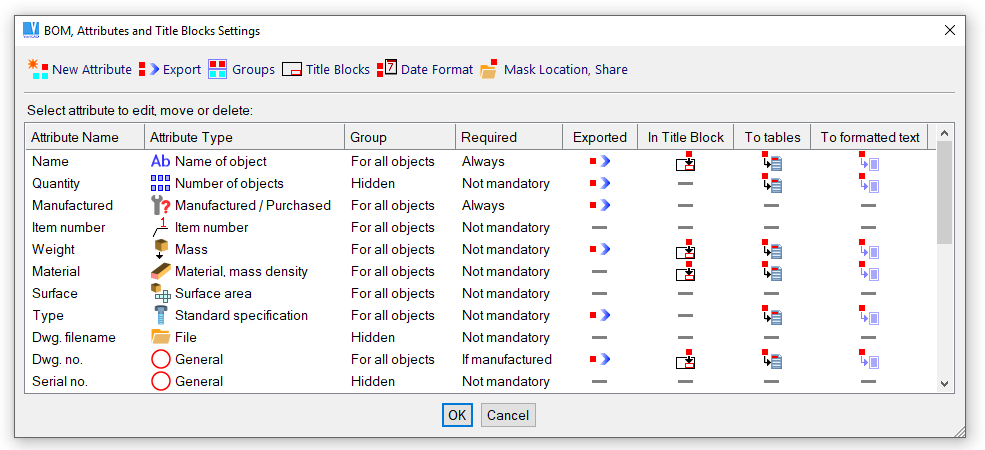
BOM, Attributes and Title Blocks Settings (Mask)
Sharing of BOM mask (BOM settings) is available, if you click icon “Mask Location, Share” in upper tool-bar of BOM mask window. When you create a BOM mask suitable for all other users, then save it into selected network path. All users need to set the same network path for loading of the BOM mask.
Each attribute has its own name. The name must be unique among all defined attributes. The name should represent the meaning of the attribute value. For instance, if the attribute defines material of a solid, then the attribute should be named “material” or similarly.
If the attributes are defined in different configurations, their names are used for recognition of compatible values – see Compatibility of Defined Attributes and Attribute Groups
The type of attribute determines the method of attribute definition or behavior. Although each attribute may be defined as an attribute of “General” type, it is always better to consider the best type of given attribute. You may use the following types:
| Name of Object – defines name for object recognition (for instance “Shaft 32-150” etc.). Defined names are usually demanded for the list of parts. If the name is not defined, the solid cannot be processed in BOM. Only one attribute of the type “Name of Object” can be defined among all available attributes. |
| Item Number – can be assigned automatically in BOM. If 2D drawing is created, item numbers of solids are automatically used as leader texts. |
| Mass – value is mass (weight) of the solid. If defined, VariCAD allows you to calculate mass of the solid using the same method as in the function “Volume, Mass, and Center of Gravity”. After calculation, you may select the result in various units (kg, g, lb., oz. etc...). |
| Surface Area – value is the surface area of the solid. If defined, VariCAD allows you to calculate surface area of solid using the same method as in the function “Surface Area”. |
| Manufactured / Purchased – value defines if the part is manufactured (documentation is created) or if it is purchased. According to this attribute, other attributes may be required as mandatory or may not be required at all. Manufactured objects may require other different attributes (like, for instance, drawing number) than the purchased ones (like, for instance, purchase code). |
| Number of Objects – for a single solid, the value is always equal to one. In BOM, the value is automatically counted as a sum of the same objects in the assembly. For the assembly, you may obtain the value as a sum of the number of objects of all parts. |
| Date – value contains a day of the month, month and year. You may configure the format of date representation, using the function BOM, Attributes and Title Blocks Settings. You can select the same representation as in the operating system or you may define your own. |
| File – value contains an existing file, usually the file containing the corresponding part or the assembly file. You may select the file name from directory listing or you may choose it from the current file or file of a part defined in the assembly link. |
| Material – value contains material of the corresponding part. If defined, you may select from previously used values or you may copy the material from another solid. |
| Standard specification – value usually contains specification of standard, like DIN, ANSI etc. This attribute is automatically defined for solids inserted from mechanical parts libraries, like for screws, nuts, bearings etc... |
| Attribute of a general type – can be used always if the previous types are not the best option. For the general attribute, you can also define more methods of value definition - see below. |
Attribute values can be:
If the attribute is defined as attribute of a general type, you may select an additional method of its value definition. You can obtain value also as:
For each attribute, you can define also:
Group membership, output to formatted text, title blocks or output to export files is described in following paragraphs.
If the attribute is listed in the Solid Attributes definition window or in BOM, Attributes and Title Blocks Settings window, you can always see usage of the attribute:
| The attribute is used in the list of parts (in formatted text files, suitable also for insertion into 2D area) |
| The attribute is inserted into title block (or more title blocks). |
| The attribute is used in text file suitable for import into other systems. |
You may create a new attribute group, or rename or delete an existing one. For an attribute, you can select or deselect a group the attribute belongs to. In the function "Solid Attributes", you can assign (or detach) the selected attribute group for the corresponding solid. The same can be done for an assembly or file in the function "Assembly Attributes, Title Block Filling".
Attribute group allows you to define different attributes for different objects. If the attribute group is defined for an object, extra attributes from this group are demanded.
For instance, you can define a group named "Sheet metals" and an attribute named "Sheet metal thickness". If you assign the group "Sheet metals" for a solid created as sheet metal, then during attribute definitions for this solid the attribute "Sheet metal thickness" is required. On the other side, the attribute "Sheet metal thickness" will not be required for a shaft.
From BOM, you can create a formatted text file that contains a list of parts. Formatting is correct if the text file uses fixed-width font. If the file is inserted into 2D VariCAD area, columns are formatted properly for the fixed-width fonts. In 2D area, you can insert such a file into predefined tables using the function "Insert Text File - TXI".
Name and attributes of each part in the list can be divided into more lines.
For an attribute, you can define:
Order of attributes written into such a formatted text file is the same as order in BOM, Attributes and Title Blocks Settings.
You can define one or more title blocks. For a title block, you can define the corresponding 2D file with the title block itself. For an attribute, you can define its insertion into the title block.
Define a title block name. The name must be unique among other defined if you use more than one title block.
For title block automatic insertion into 2D area, define:
Once properly defined, VariCAD inserts the title block automatically into the desired 2D location whenever necessary.
For an attribute, you can select the title block the attribute is displayed in. One attribute may be displayed in more title blocks. Then define:
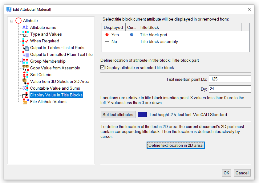
Attributes to title blocks
From BOM, you can create a text file suitable for other systems, like spreadsheets. Order of attributes written into such a text file may be different than the order in BOM, Attributes and Title Blocks Settings. From the list of attributes, you can define if the selected attribute is exported or define its order among the other exported attributes.
The name and attributes of each part in the file are written into one line. For export, you can also select an extra object - a level of insertion. In such case, the value determines whether the object in the line represents a part or assembly.
You can define a format of the text file:
Before you will use the attributes, BOM and title blocks permanently, you should consider their proper configuration and change the settings according to your customs. The file containing the settings is a part of VariCAD distribution, but you should take it rather as an example. The settings are initialized when they are used for first time. From then, the attributes are recognized automatically. You may change their names (not only their values) and VariCAD always accepts them properly.
To allow such behavior for more users in one company, you must use the only one configuration file. The best option is to save the settings into location accessible via local area network. In the function "BOM, Attributes and Title Blocks Settings" select the option:
| Change Path. You can load the settings from the selected directory (or LAN site). Next time you work with BOM, attributes or their settings the configuration is loaded from or saved to this directory. You can also redefine the configuration site saving the configuration into a selected path. |
If you work with files created according to other attributes settings, the attributes match your settings only if they have identical attribute names (lower/upper cases are ignored).
If the solid attributes in files are defined according to an old attribute mask (in VariCAD versions older than 2007-3.00), they are recognized properly, too.
Compatibility of defined attribute groups follows the same rules as compatibility of attributes.
BOM contains a legible list of assembly parts, their names and attributes. BOM allows you:
You can create BOM using three following methods – at a basic level, containing assembly or from 3D groups.
Create BOM at Basic Level – BOM, Ctrl + E |
Each BOM object is a part belonging to the current assembly (to the current file). All objects are displayed at one level. All displayed objects are exported to files.
If the current assembly contains inserted sub-assemblies, you can select from following options:
| BOM is created from highest level only. Objects creating sub-assemblies are not displayed. |
| BOM is created from all levels, including sub-assembly items. All objects are displayed at a single level. This method is useful, if you need a list of all parts and sub-assemblies from the current highest assembly. |
| BOM is created from all levels, only from single parts. All objects are displayed at a single level. This method is useful, if you need a complete list of all single parts necessary for manufacturing of the current assembly. This list of parts contains, of course, parts used directly in the highest assembly and also parts used in all sub-assemblies. It is a summary list of parts. |
Create BOM Containing Assembly – DSS3 |
The first object in BOM is the current assembly; the next objects are the parts belonging to this assembly.
If the current assembly contains inserted sub-assemblies, you can select from following options:
| BOM is created from all sub-assembly structures. BOM displays legible structure of the entire assembly and sub-assemblies, down to the lowest level. |
| BOM is created from the highest assembly level only. BOM displays the highest current assembly and all objects at the highest level. |
Create BOM from 3D Assembly Group – BOMG |
Each BOM object is a part from the current assembly (from the current file), same as the BOM creation at basic level. Only parts belonging to the selected solids group are inserted into BOM.
3D groups were used as a substitution of sub-assemblies, so the selection of one particular group can be used for BOM created for corresponding sub-assembly. However, this method is obsolete and is meaningful only for VariCAD files created in old versions.
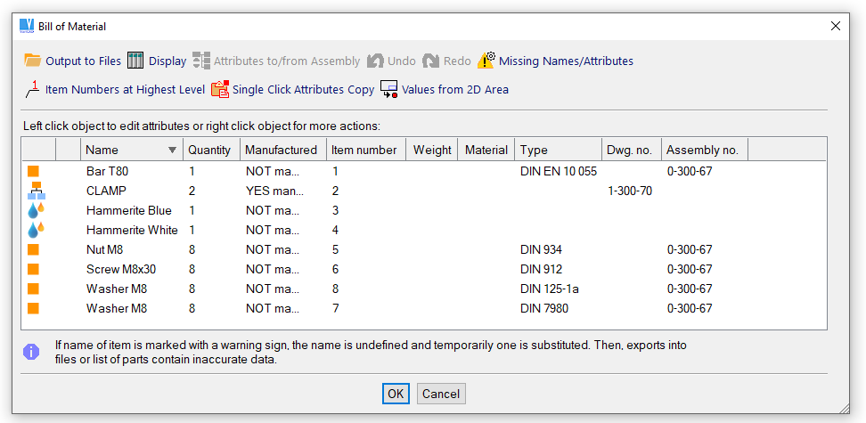
BOM object is either the current assembly or a part of the current assembly. It is listed in one BOM line. Object's name and attributes are arranged in the corresponding columns. Right clicking an object, you can:
Left clicking an object, you can edit its attributes.
BOM objects are distinguished by different icons. These icons are identical with icons used in assembly tree structure window, see 3D Assembly Tree Scheme Window.
Following examples contain BOM created from the same assembly, by different methods:
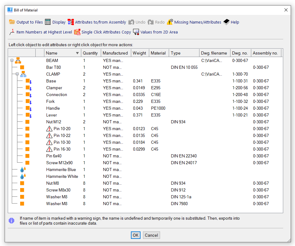
Bill of materials, created as complete assembly structure
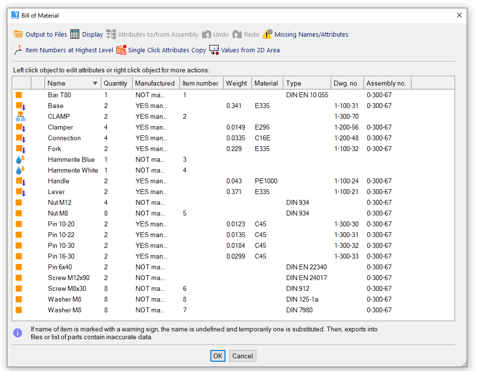
Bill of materials, created as complete list of single parts at one level
Bill of materials, created as highest assembly only
To sort objects according to selected attribute values (or alphabetically according to names) left click the header of the attribute column.
You can use more options to define how the objects are displayed:
| Display Columns. This function can be selected from the pop-up menu, or performed after right click the list header. You can select an attribute to display values in the column or deselect an attribute from displaying values in the column. You can also select the attribute the entire list is sorted according to. |
| Filtering Objects to Display. It is possible to define filters for displaying objects. Filter allows you to display objects with a certain range of attribute values or to display objects with attribute values containing defined character sequences. For instance, if you want to create a list of all screws in the assembly, define a filter for object's name containing sub-text "screw". |
You can create output to following files:
| Output to Formatted text, see Output to Formatted Text (List of Parts). |
| Attributes Output to Part Files. Data are suitable for the title block filling. To fill part title blocks after attributes export, perform function Assembly/Part Attributes, Fill Title Blocks for each file containing the corresponding part. |
| Output to Text Files. The output is suitable for other systems, like spreadsheets. See Export to Other Systems. If the BOM is created from assembly and contains sub-assemblies, you can select between export from the highest level or from all levels. |
If the BOM is created as BOM containing an assembly, extra options are available:
| Attribute Values from Assembly. Some attributes may have defined option "Copy Value from Assembly". For instance, a value of the attribute "drawing number" from the assembly is a value of the attribute "assembly number" in the part. This function copies the attribute value from the assembly into the corresponding attribute of each part. If the BOM is created from assembly and contains sub-assemblies, there are two options. You can select export from the highest assembly into all lower objects, or export from each sub-assembly to one level down. |
| Sum of Attribute Values. For attributes with the corresponding option, value in the assembly is sum of values from all parts. Weight of the assembly is obtained as sum of all weights of parts. This function defines attribute values of the assembly as sum of corresponding attributes of the parts. |
To define item numbers in BOM, your BOM mask must contain attribute of type “Item Number”. Then, you can assign item numbers to objects in assembly, at the highest level. After creation of 2D, item numbers are automatically used as leader texts.
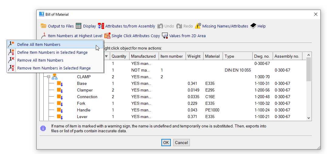
BOM menu containing item numbers definitions
| This command opens attributes window. Then, define attribute values. After definition, click BOM line by line. Defined attributes are added to each selected line. Optionally, all BOM lines can be modified at one step. Some attributes or names cannot be defined this way. This method is convenient for definition of attributes common for multiple solids, like Manufactured-Purchased, Date of creation etc. |
| This option allows to copy attributes from 2D area of each part drawing. As an attribute, you can copy 2D drawing format and/or 2D drawing scale. Attributes can be updated line by line, or for all objects at one step. 2D drawing format or 2D drawing scale as an attribute must be enabled in BOM mask. Both values can be further used for copying into 2D drawing title blocks of parts (details). |
Supplementary Objects - SPO |
You can define supplementary objects for the current document. Supplementary objects are all objects not created as 3D solids. Typical example is oil, paint, welding electrodes etc. In BOM, all supplementary objects are at the same level as the other 3D solids. They are correctly listed in the BOM exports, a list of parts or wherever assembly parts appear.
Working with supplementary objects interface is similar to working with BOM. You can add, delete or edit a selected object.
Solid Attributes - SAT |
Define new attributes, change existing attributes or delete attributes of a selected solid. Attributes are defined according to the BOM, Attributes and Title Blocks Settings. If you need to define mass or the surface area, there are geometric calculation functions available. Using the “Number of Items” attribute is not relevant when creating a BOM from 3D. In 3D, the number of items is defined automatically as the exact number of currently existing parts.
You can also define an attribute group or groups for the selected solid. Then you may define extra attributes belonging to the selected attribute group.
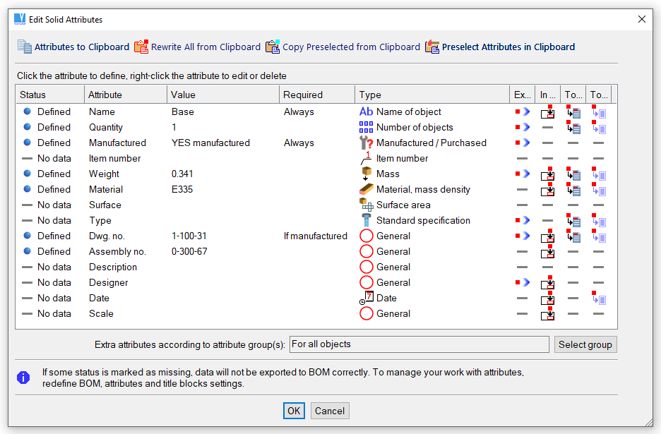
Solid attributes definition
Attributes can be put into a clipboard. Then, these attributes can be copied into another solid. You can rewrite all existing attributes, but more likely, you may need to rewrite only some attributes. Typically, it may be date of creation, author of project or similar attributes, usually common for multiple solids.
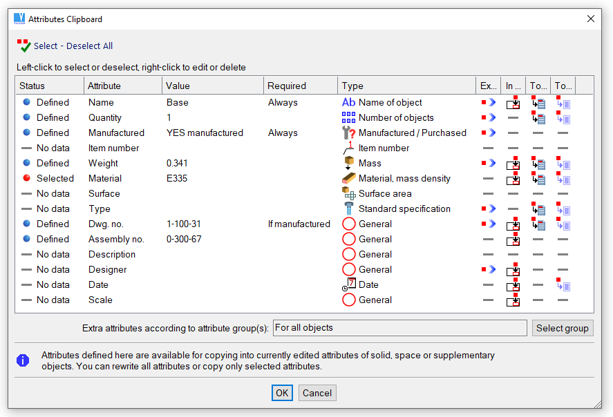
Solid attributes clipboard
Attributes from List - ATL |
Define attributes from the displayed list of solid names or attributes. The solids that use a selected value are highlighted. From the highlighted group, select the object whose attribute you want to change. This function changes attributes of each object individually.
Change Identical Attributes - MTC |
Changes one attribute value to a new value for all objects. First, select the attribute from the attributes list. Then select the old value, enter the new value, and all old values will be replaced with the new ones. For example, you can select the attribute “material” and replace all instances of one material with another.
Check Attributes - ATC |
You can choose to check for missing names, missing attributes, or missing attributes according to their definition – see BOM, Attributes and Title Blocks Settings. If objects with missing desired values are found, attribute definition is performed. You can exclude objects from attribute checking, so that these objects are ignored during next checking.
For definition of solid attributes and BOM data, material of solids can be selected from a list of materials. The list of materials is distributed as a part of VariCAD package. However, the distributed list is rather schematic and short. Each user can add materials used in his company, or edit existing data. Materials in list are sorted into material groups.
Together with material designation, each material contains definition of mass density and other optional data. By other words, if a material is once defined for a solid, you don’t need to define mass density later. Mass density must be known if you want to calculate mass of solids.
Optionally, materials contain definition of colors. In settings of display of solid colors and wires, you may turn on a display mode, when solid colors correspond to solid materials. For solids without material definition or materials without color definition, a specific common color is used.
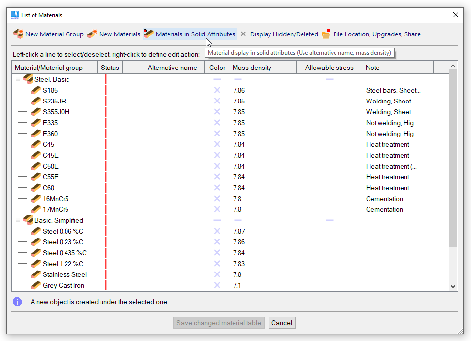
Define or Edit List of Materials - DMAT |
This command manages list of materials. You can run it also from system settings – command “CFG”, from General section, “List of Materials Settings”. Here, you can delete user-defined list of materials. If the user-defined list is deleted, a new one is created as a copy of list distributed in VariCAD package.
To create a new material, right-click a line and select, whether the new material is inserted above or under it. You can also click a corresponding icon at upper row of icons. To create a group of materials, or to edit or delete material or group, click a line and select a step from pop-up menu.
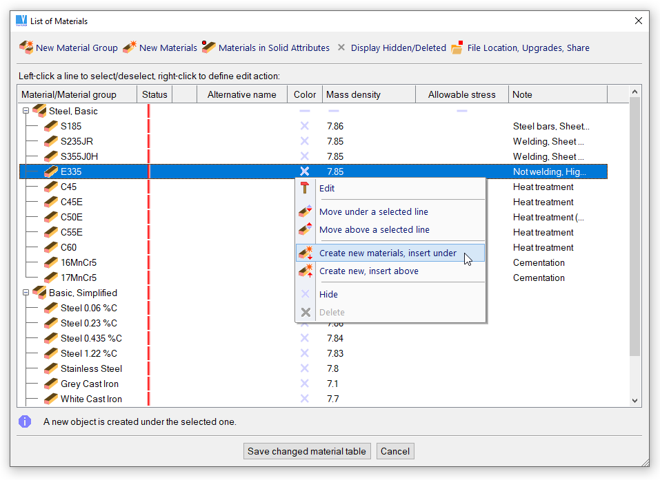
New material will be inserted under a selected line
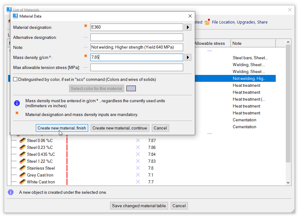
Definition of a new material
Status is displayed in second column of the list. Icons can contain combination of multiple situations.
| Newly created |
| Edited |
| Scheduled for delete. It is shown only, if you turn on “Display Hidden/Deleted” |
| Hidden. It is shown only, if you turn on “Display Hidden/Deleted” |
| Hidden, original data. It is shown only, if you turn on “Display Hidden/Deleted” |
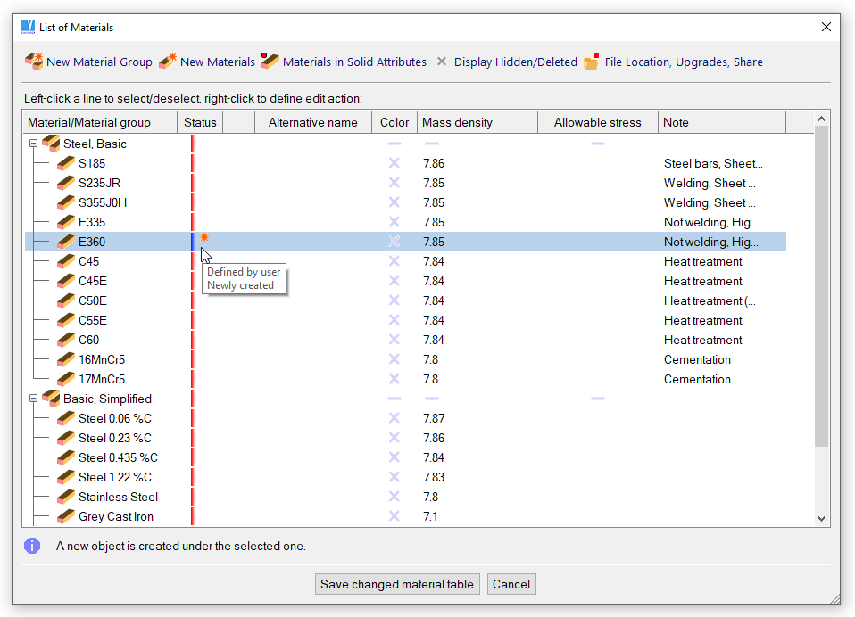
Example of status of material
Data (materials or groups of materials) in table may be original or user-created. Original data are updated from VariCAD distribution. They cannot be deleted or renamed. They can be hidden, or partially edited.
Optionally, you can stop updating of list of materials and to manage it completely at your own. In such case, all data have status of user-defined.
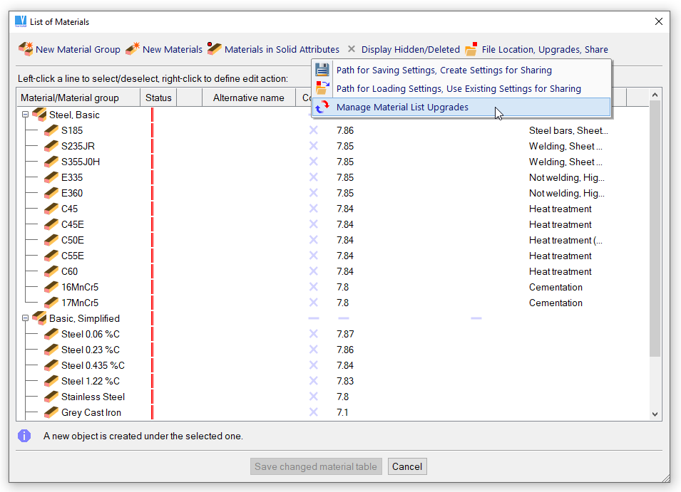
Selection of update options of list of materials
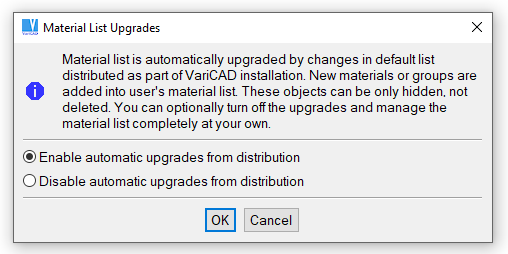
Update options of list of materials
Sharing of list of materials is available from the same menu as you can select update options (see above). If you create a material table suitable for all other users, then save it into selected network path. All users need to set the same network path for loading of list of materials.
It is possible to select, how materials are displayed in list of solid attributes.
Selection of attribute display options
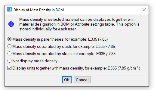
Options of material display in list of solid attributes
To define material as a solid attribute, you can:
It is always mandatory to define material designation and mass density.
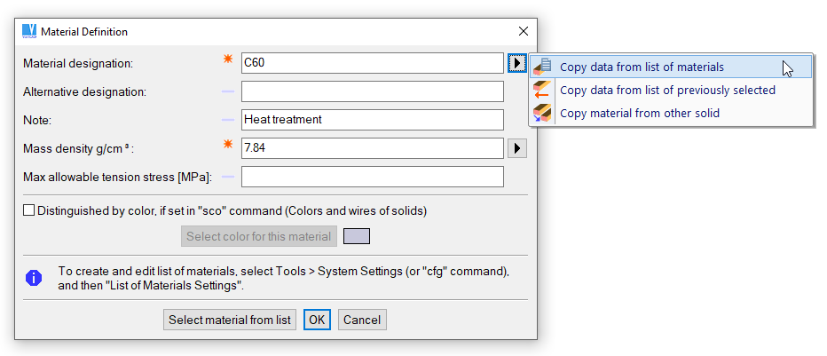
Definition of material as a solid attribute

Table of mass densities
Define Mass Density or Material - MAT |
This command allows you to define mass density and material for a group of selected solids. Although the material can be defined as a solid attribute, you may define it separately from attributes management.
Mass density is stored for each solid together with material. If a mass of an assembly is calculated and different materials of different parts are used, the calculation copes this correctly. If some or all solids have no material defined, mass calculation asks for mass density. Then, entered value is used only temporarily for the calculation.
Assembly, Sub-assembly or Part Attributes, Fill Title Blocks - AAT |
Define new attributes, change existing attributes or delete attributes of the current file – assembly, sub-assembly or part file. Attributes are defined according to the BOM, Attributes and Title Blocks Settings, the same way as in the function "Solid Attributes", described above. If you define attributes of a part file containing a part from assembly links, the attributes are defined exactly for this part. Otherwise the attributes are connected to the current file instead to a solid. This function also allows you to fill title blocks.
If the current file is a sub-assembly, the file attributes are solid attributes of integrated sub-assembly, whenever the sub-assembly is inserted into an assembly.
Fill Title Block, Define Attributes - AAT2 |
Similar function as the previous - available in 2D.
Select a title block first. If you have defined only one title block, then the selection is skipped. If the title block has no corresponding file defined or if the corresponding file was not found, then you cannot insert the title block into 2D. You can only insert 2D text objects representing attribute values (name, date, material etc.) relative to title block's insertion point.
Automatic insertion of the title block is possible, if you need the title block always at the same location relative to one of four corners of the drawing area. Insertion of attributes uses 2D text properties defined in BOM, Attributes and Title Blocks Settings. The title block location and location of texts are defined in the same function.
| Fill Title Block – only fills the selected title block. If started in 3D, VariCAD switches itself into 2D. Then select a title block's insertion point. All defined attributes are inserted into predefined locations in the title block area – 2D text objects are created. |
| Update Title Block – fills or updates the selected title block. If the title block was filled previously, the old objects are automatically removed first. The other is the same as in the previous option. |
| Insert Title Block - if the selected title block does not exist, then it is inserted automatically. All defined attributes are inserted also automatically into predefined locations relative to the title block's insertion point. If the title block is already filled, the old objects are removed first. |

|
|
|