For Windows users, VariCAD enables you to print to devices that use Windows drivers. Linux users can use Qt print capabilities. All users can always use VariCAD print drivers as well.
There are multiple ways to define the printed area:
By default, the area is rotated so the longer side of printed area will be parallel to the larger side of the printed sheet. There are following additional rotation options:
By default, the sheet size is the same as drawing format, or the maximum size allowed by the printer. There are following additional sheet size options:
By default, scaling is disabled, but you can select scaling options:
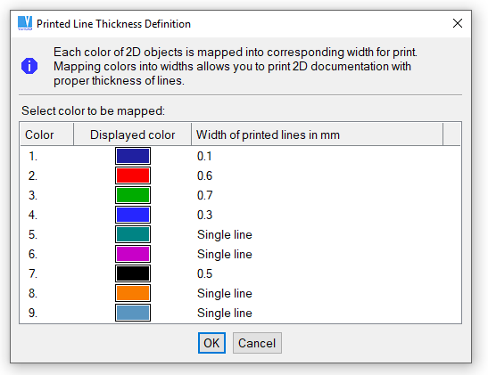
When using a color printer, you can map the display colors to printer colors. For standard printers, you can always map display colors to print line thicknesses. The result is different if the colors are mapped first. Line thickness and color mapping can be done within the Print Settings function, or in command “CFG”, in 2D section.
Definition of thickness of printed lines
If you are in 2D mode and if you select a printing command, the 2D area is printed according to print output settings. If you are in 3D mode, shaded or wire-framed objects are printed. For 3D printing, consider selection of enhanced rendering and especially, pure white background – similarly as for output of bitmap images – see Exporting Images as Bitmaps.
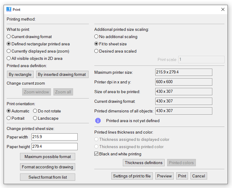
Print output selection, 2D environment
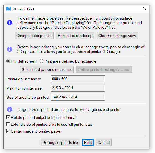
Print output selection, 3D environment
Print to System Printer - WPS |
Print - WPR, Ctrl + P |
Select a printer from the list of printers available in your operating system. The driver of each printer must be installed and set properly.
Print, VariCAD Drivers - PRN |
This method is obsolete and no longer developed. It should be used only as a substitution in case the proper print system drivers are not available, or in case of an old hardware.
It creates output to any device using PostScript, HPGL/2, HPGL, PCL5 or Epson formats. You can select a printer listed in the window, or a printer compatible with any listed device. You can save your output to a file, or you can change or define the printing command of your operating system.
During printing, the operating system sends a temporary file to the printing device. In the command, the filename must be replaced by the sequence %s. For example, “copy %s LPT1 /b” is the Windows command for sending data to the parallel port. Default commands are predefined for this method of printing.
Batch printing is used for printing of multiple files at once. First, select the files to print. Then define the method of printing. Print settings can be defined for each file individually or for all files, and settings are the same as for single prints. See Print Settings.
Once defined, batch print settings can be saved to a configuration file, which lists all printed files and their settings. If you need to print multiple files again, you can use this batch configuration file.
Batch printing is handled by the following functions:
Batch Print, from Predefined List - BPRP |
Batch Print, or Define List to Print - BPRW |
Batch Print, VariCAD Drivers - BPRV |
Bitmap File from 3D - BMP |
You can create a bitmap file as a content of 3D display. The image is saved into PNG format, or optionally into BMP format in true color mode (24 bits per pixel), into JPEG format or into GIF format (into GIF only under Windows). We recommend to use the PNG format, because this is compressed format without any loss of original quality. This aspect is important especially for any images scanned from computer screens.
Before the file is saved, the following properties can be set:
Before the bitmap image is created, you can check objects displayed inside the output area (full screen or defined rectangle). The display can be finally changed by standard functions like zoom, pan or view angle. If you need to change displaying from standard to enhanced (allowing perspective, light position changes etc.) or if you need to change the color palette, perform these changes before the bitmap output function is called.
If the bitmap file is prepared for printing, then consider color palette changes – especially the background color. Installation package of VariCAD contains a set of color palettes, containing a palette named “3D printing”. We recommend to select this palette. The white background should have pure white color (RGB coordinates equal to 255, 255, 255).
The white background is usually the best option for printing of 3D images. Number of pixels (or dots number) for printing should be set according to the paper size, printer settings (dpi) or color vs. grey scale printing. 1000 dots per 100 mm or 2500 dots per 10 inches give you reasonable sufficient quality of the printed document.
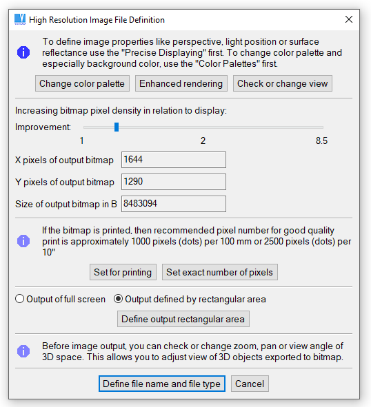
Bitmap creation

|
|
|