You can change the shape of a solid created by rotation, extrusion or lofting of a 2D profile, when you define constraints and parameters for objects of the profile.
You can define constraints for a group of vertexes. Vertexes are:
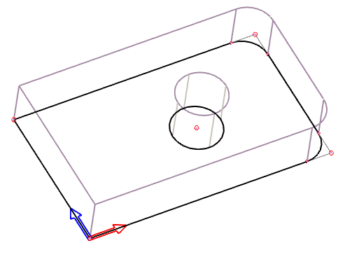
Vertexes of a solid creation 2D profile
If you need to work with 2D creation profile constraints and parameters, select a solid for editing. Then click the corresponding icon in the edit toolbar – 2D edit mode is switched to profile constraint mode. After performing a change, the profile is always edited in constraint mode. From constraint mode, you can switch editing back to 2D edit mode similarly – clicking an icon in the constraint toolbar.
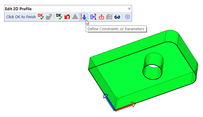
Switching 2D edit mode to profile constraint mode
Vertexes can be constrained at a distance to the center of coordinates or to another vertex (to an anchoring point). The distance may be a constant value, parameter or an expression containing parameters. If the corresponding parameters are changed, position of vertexes is relocated.
Vertexes can be constrained in direction of X axis, Y axis or in radial direction. Constraints can be defined for X axis and Y axis independently. However, if vertexes are constrained in radial direction, then constraints in x-direction or y-direction are not available and vice versa. Trying to define such an unavailable constraint, you are informed that the existing constraint will be overridden.
A constraint is defined for a group of one or more vertexes. After selecting vertexes, define a referent point. The constrained distance is a distance from the coordinate center or anchoring vertex to the referent point (vertex). All other vertexes are moved together with the referent point, if the constrained distance is changed.
| Icon | Method |
| Constrain objects in X direction to the coordinate center | |
| Constrain objects in X direction to another object | |
| Constrain objects in Y direction to the coordinate center | |
| Constrain objects in Y direction to another object | |
| Constrain objects under an angle and distance to the coordinate center | |
| Constrain objects under an angle and distance to another object | |
| Changes definition of an arc: 2 points, radius vs. 2 points, radius, and center | |
| Change a chamfer distance | |
| Change a radius of an arc, circle or fillet | |
| Display constraints and coordinate systems | |
| Check profile dimensions | |
| Edit an existing constraint | |
| Delete an existing constraint | |
| Edit an existing coordinate system | |
| Redefine the coordinate system for the created constraint. X-Y coordinates are defined under an angle. | |
| Finish editing | |
| Skip editing and set creation properties | |
| Back to 3D, unchanged |
You can select vertexes clicking them one by one, or use following options:
| Select vertexes inside the selection window |
| Select vertexes outside the selection window |
| Toggle between adding and removing from the selection set |
If certain vertexes cannot be selected, they are displayed in different colors. Selection of some vertexes can be blocked, if:
You can also pick a set of vertexes first, finish the selection and then select a following step from pop-up menu.
Working with a 2D solid creation profile, you can change display similarly as in edit mode:
| Toggle between thick and thin outlines in 2D |
| Toggle entire display between shaded and wire-framed |
Radius of a circle, arc or fillet can be defined as a parametric value. Chamfer distances can be also defined as parametric values. It is not necessary to define a constraint to change a value of radius or chamfer distance. Select an object and redefine the value.
Rounded or chamfered corners are detected as filleting or chamfering, if the blend operation was performed in 2D edit mode in 3D environment. If the profile was created in 2D drafting module, only filleting of two linear segments is recognized. In case of a rounded or chamfered corner, the end-point vertex is at location of the original corner. Connection of a fillet arc or chamfer line to the original linear or arc profile segments is displayed differently. The connection cannot be selected for constraint definition, but can be selected for values measurement.
By default, arcs are defined by two endpoints and radius. If necessary, you can add the arc center to the definition. In such case, the endpoints must be explicitly calculated if they are constrained - otherwise they may not be at the radius distance from the arc center.
An exception of constrained endpoints of circular arcs is a situation when the endpoints are constrained only in x-direction or in y-direction. For example: if an endpoint is constrained in x-direction, the x-coordinate is exactly defined. If this point is an endpoint of a circular arc, its distance from the arc center is also exactly defined. The y-coordinate of such an endpoint is recalculated after change of an x-constraint or radius of the arc. According to a corresponding geometry, there may not be a solution. If the solution exists, a new arc endpoint location is defined.
NURBS curves are created as interpolation curves defined by a set of points. The shape of the curve can be modified, if you change locations of the interpolation points. The interpolation points can be constrained as other vertexes – either each point individually or the set of points as a constrained group.
To edit a constraint, select a vertex first. If the vertex is a member of two constrained groups (for instance, a group constrained in x-direction and a group constrained in y-direction), select which group is edited. Add or delete vertexes to or from the selected group. Finally, confirm or edit the constrained distance. It is not possible to change the reference or anchoring point, if the edited constraint is constrained to another vertex.
Select a vertex from a constrained group to be deleted. Confirm removal of the selected group.
By default, the world coordinate system is used. X axis is directed to the right, Y axis is directed up. Location of the center of the coordinate system is defined during profile creation. If necessary, you can redefine the coordinate system for a group of selected vertexes. The coordinate system can be defined with following methods:
| Center at a selected vertex, X-direction to a selected vertex |
| Center at a selected vertex, X-direction under a defined angle |
| Center defined by XY, X-direction to a selected vertex |
| Center defined by XY, X-direction under a defined angle |
| Reset the coordinate system to default |
If the center coordinate or X-axis angle is defined, you can use parameters instead of constant values. If the center position or X-axis angle is changed, position of all vertexes in the group is recalculated, too.
If the coordinate system for a set of vertexes is redefined, you can create a constraint only for vertexes with identical coordinate system.

|
|
|