Many 3D solids can be created by extruding, rotating or lofting 2D profiles. Other basic solids such as cylinders, boxes, cones or pyramids can be defined by entering dimensions. Nearly all mechanical parts contain basic solids, which can be joined and/or trimmed. Combining and subtracting solids are called Boolean operations, and resulting solids are called “Boolean Trees.” VariCAD provides tools to add solids and to use one solid to cut another, either keeping or deleting the cutting solid. Commonly-used Boolean operations such as drilling holes, creating grooves, and cutting by a large box are also available. Blending functions are provided for rounding and chamfering solid edges.
Following two chapters describe how to create basic 3D solids, which can be later combined into Boolean trees.
When using a 3D solid creation method that requires a 2D profile (or multiple profiles in multiple planes) as an input, the profile is created in sketching plane in 3D space. Optionally, you may select a profile in 2D area; however, such method is limited only for solids created by single profile in one plane. In sketching plane, the profile is created by standard 2D drawing features. See Sketching - 2D Drawing in 3D, Drawing Methods. If a solid shape is edited, the profile is always modified in sketching plane.
Before you start sketching of a profile, you must define the sketching plane. It may be selected as:
An existing plane at a solid can be conveniently selected, if you press and hold Ctrl + Shift and move cursor over a planar solid’s surface. Plane’s outlines are highlighted and the plane is selected by left click. Outlines are pre-defined as an existing profiles 2D objects.
| Sketching (2D Drawing Projected into 3D Space) - DRP |
Generally, sketching is started if you click the corresponding icon between icons used for activation of 2D or 3D mode.
If you start creation of a solid defined by profiles extrusion, rotation or lofting, a pop-up menu appears and you can select sketching plane. If you select an existing solid for editing, the sketching plane is defined automatically according to solid location.
After sketching plane is selected or a solid is selected for profile editing, VariCAD switches environment into sketching mode. Toolbars are changed. You can use standard 2D drawing commands, with certain limitations – see Sketching - 2D Drawing in 3D, Drawing Methods. A solid can be created from multiple profiles in multiple sketching planes. Undo or Redo of 2D commands is available for each sketching plane separately.
Sketching can be finished, if you:
Commands specific to sketching are available from sketching toolbar or from pop-up menu, which appears if you right-click an empty location.
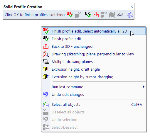
Toolbar and pop-up menu, solid profile creation
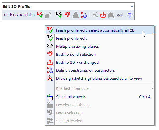
Toolbar and pop-up menu, solid profile editing
If you want to create a new solid and sketching has already started, you can create 2D objects of a new solid’s profile. You have to select a method of solid creation. You can do this whenever during sketching, or at last when you finish the profile. According to creation method, you must also define solid’s extrusion height or rotation angle, draft angle etc. Again, such values may be defined during sketching, or at last at the end of sketching.
To see how the new solid looks like, extrusion height or rotation angle is predefined. You must define the final value whenever during sketching.
Available methods of solid creation from 2D profile or profiles:
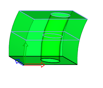
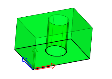
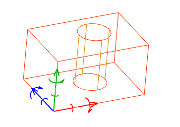
Created or edited solid is displayed as a transparent object. By default, the shape is permanently updated after each change of the profile’s shape. If a solid can be created from all 2D profile objects, it is displayed in green color. If the created or edited profile contains an error (like intersections of lines or gaps between lines’ endpoints), the solid is displayed in red color at the last correct position.
In case of erroneous profile, or whenever a solid cannot be rebuilt, you can click a corresponding icon and display what caused the problem. On the other side, if the profile is correct and the solid can be created, you can finish profile creation and skip selection of profile’s segments – all 2D objects are selected automatically.
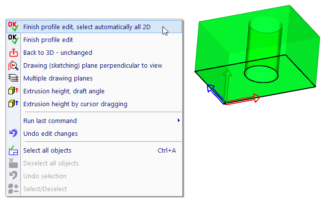
Example of correct profile. All 2D objects can be selected automatically.
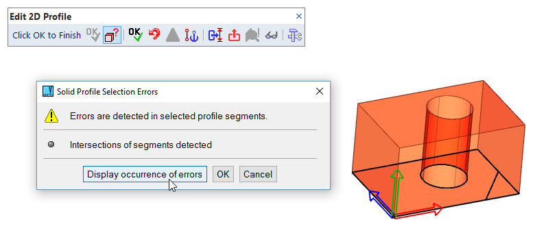
Example of incorrect profile. Occurrence of errors can be displayed.
It is possible to manage how the edited solids are displayed. Wire-framed display can be used instead of transparency, or a solid may not be updated permanently.
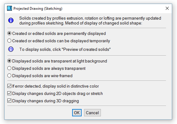
Settings of display of 2D profile sketching
A solid may be created from multiple profiles. Then, each profile is created at a separate sketching plane. To select features related to multiple sketching planes, click XYZ axes of the current sketching plane and select action from menu.
In case of multiple sketching planes, only one plane is active. 2D objects are created or edited in active plane. Sketching plane is activated, if you click its contours.
First sketching plane is so called a base plane. This plane becomes active automatically, whenever the solid is edited. XYZ axes of the base plane are axes of the created or edited solid. If planes are copied or created as new planes, all planes must be above or under the base plane.
Create, Copy or Transform Drawing Planes |
This command manages sketching planes. It may be especially useful if a sketching plane does not contain any 2D objects. Because then, you cannot click its contours.
Following features are available at pop-up menu, after you click contours of inactive sketching plane or XYZ axes of active sketching plane:
| Activate a sketching plane. |
| Copy a sketching plane together with all 2D objects. A new sketching plane is transformed and located the same way as a new or transformed solid. |
| Copy a sketching plane without 2D objects. |
| Delete a sketching plane. Base sketching plane cannot be deleted. |
| Transform a sketching plane. If transformation is selected for a base plane, the rest of sketching planes and consequently, entire solid is transformed. Otherwise, the transformation changes position of the sketching plane relative to other planes. |
| Defines distance from the base plane. The selected plane is then parallel with the base plane and its coordinate center is exactly above the center of the base plane. Distance can be defined also as a mathematic expression containing parameters. |
| Defines angle from the base plane. The selected plane is then rotated around X axis and its coordinate center is at a location of the base plane center. Angle can be defined also as a mathematic expression containing parameters. Angle between planes must not be greater than 60 degrees. |
When a plane with 2D objects is moved or copied, created solid is recalculated permanently and if cannot be rebuilt, it is displayed in red color at the last correct position. Planes are sorted automatically, if you move a plane.
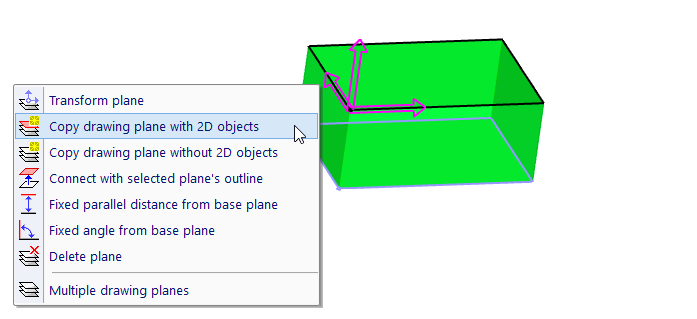
Sketching plane’s options, copying is selected
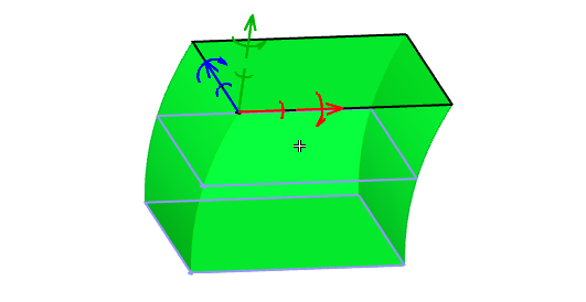
Sketching plane is copied together with 2D objects
To copy 2D objects among the rest of sketching planes, select the objects. Then, right-click and from related sub-menu, select method of copying:
| Copy and add to rest of drawing planes |
| Copy and replace objects at each drawing plane. This feature is useful if all planes contain the same profile and if you need to change profile’s shape. |
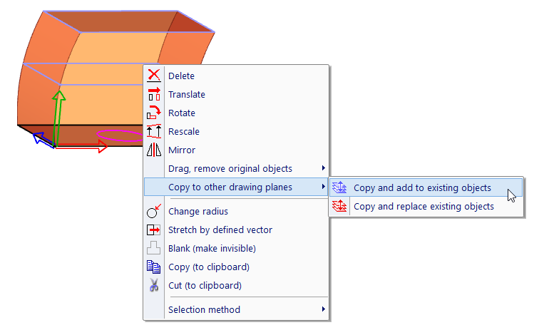
Copying 2D objects among sketching planes, selection of 2D objects
Edited solid after the 2D object is copied
Generally, a set of 2D objects can be whenever and wherever copied, using Copy and Paste (Ctrl + C, Ctrl + V).
These features can be selected from toolbar, or if you right-click an empty location.
| Finish profile edit, select automatically all 2D objects. This command finishes edit. If you already defined values like extrusion height or rotation angle, entering of them is skipped. If you already transformed the base sketching plane or if a plane was selected as a planar surface of a solid, transformation of new solid is also skipped. |
| Display errors in created profiles. This option is active if a solid cannot be rebuilt. Otherwise, it is inactive and active is the previous option. |
| Quit sketching without any changes of edited solid, or without creation of a new solid. |
| If active, tilt of current sketching plane is too large. By other words, you would draw 2D objects to plane almost parallel or parallel with angle of view. Although you may continue, it is better to rotate view properly. |
| Preview of created solid – can be used only, if permanent changes of a created solid are turned off. |
| Settings of display of created solid. |
| Finish profile edit. This command finishes edit. It is not available for solids created in multiple sketching planes. In following steps, you must select profile’s segments by cursor or by selection window. Then, define solid location, if a new solid is created. |
| Returns back to selection of solid to be edited. It is available only for editing of an existing solid. |
| If active, edited object is affected by constraints. Any change may cause additional transformations of other solids. |
| Define parameters and constraints within the current profile. This is available only for editing. If selected, sketching mode is finished and you can define constraints and parameters among profile vertexes. |
| Skip profile editing and set extrusion height or rotation angle of edited solid. |
These features can be selected from pop-up menu, if you click XYZ axes of the active sketching plane, or if you right-click an empty location. These features are specific for selected solid creation method (or for method the edited solid is created according to).
| Connects the active plane with a plane selected at a solid. This is another method of sketching plane creation, used for multiple planes lofting. This feature is also available as a separate command. |
| Redefine rotation axis. Rotation axis is the X axis of solid axes and simultaneously, base sketching plane axes. If you need to change the solid profile relative to rotation axis, you can move 2D objects. Sometimes, it is necessary to redefine the axis in space. To do so, define first and second point of axis. These points are defined in active sketching plane. |
| Change direction of the rotation axis. The profile of rotation solids rotates around X axis counterclockwise. It means that if the X axis is directed toward you, the rotation is counterclockwise. This command reverses direction of axis and consequently, direction of profile rotation. |
| Move all 2D objects to axes origin. Center of all 2D objects is moved into origin of solid axes. This feature is important for creation of helix. Here, the radius of helix is measured from axes origin. Consequently, it is necessary that the profile has its center equal to coordinates center. |
Profiles are created by 2D lines, circles, arc segments or NURBS 2D curves. There are two methods of profile detection:
| Detect Profile Segments (or press E) - define the profile segment by segment |
| Detect Profile (or press F) - select one segment and the entire chained profile is detected |
Apart of automatic detection of profile’s segments, you can select objects with standard methods of 2D selection – see Selecting 2D Objects. Press Enter or right-click to finish the profile definition.
Profiles used for 3D solids must be continuous. If multiple profiles are used, they cannot intersect; one profile must completely encompass the other profiles. Profiles used in a Revolve operation cannot intersect the revolving axis. Lines, circles or circular arcs can be selected for all type of solid creations. If a profile contains gaps or intersections of segments, you can optionally highlight a location of the error.
Solid insertion point is equal to center of XYZ axes of base sketching plane. For solids created from a single profile, the base plane is the only sketching plane. During profile creation or editing, you can transform the sketching plane. Together with the plane, the entire solid is transformed, too. If profiles are created in sketching plane in 3D, the solid insertion point is defined automatically.
Axes of sketching plane
Transformation axes of the solid
Transformation axes are identical with axes of the base sketching plane, until you define their new location – an XYZ offset from the original location.
Prior to selecting a 2D profile, it is necessary to enter values like extrusion height or rotation angle. Along with these parameters, you can also identify the solid insertion point and set the X axis direction. If you do not select an insertion point, the point at lower left point of profile will be used. If you do not set the X axis, the default 2D X axis will be used. The insertion point and X axis direction are used when inserting the solid into 3D space.
Run “CFG” command to select whether the insertion point and X axis direction is defined automatically, if a profile is selected in 2D mode.

|
|

|