All mechanical parts can be found on the Parts menu. The following parts are available:
The parts are created according to the following standards:
All parts have predefined default names and attributes. The names indicate the part definition and basic dimensions according to the chosen standard.
Select the standard and the type of part (screw, washer, etc.) from the Parts menu. The icon menu appears from which you can select a specific part, such as a hex bolt. To define the dimensions, you can select:
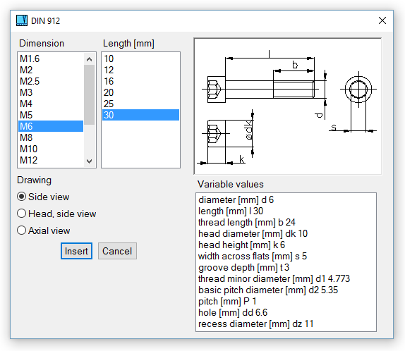
When defining part dimensions in 2D, you can also select the method of drawing or which view of the part will be inserted. For example, when a rolled profile is defined, you can choose whether or not to hatch the section. When defining a screw, you can choose to insert the front view, left view (axial view), and head.
Mechanical parts are inserted as blocks, and have predefined connection points. For details on inserting blocks, see Insert Block.

Mechanical part selection - 2D screw (bolt)
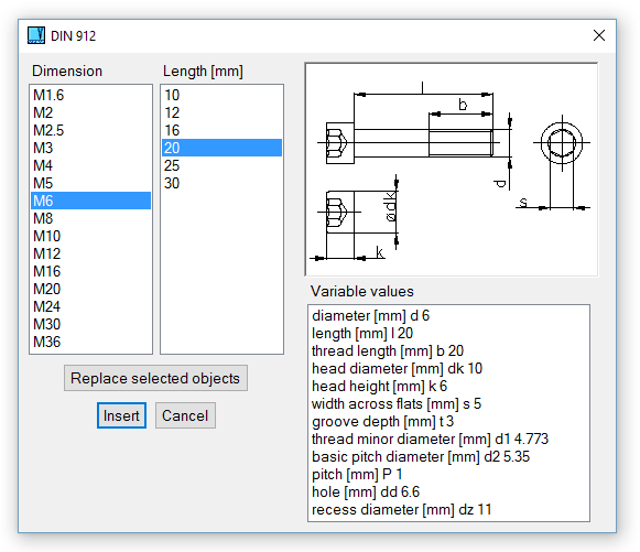
When defining part dimensions in 3D, you can:

Mechanical part selection - 3D screw (bolt)
Mechanical parts are created according to respective standards and they should not be modified. If you attempt to edit shape of library mechanical part, warning message is displayed. Rolled profiles can be edited without any warning.
If possible, some mechanical parts have defined method of cutting or trimming other solids. For example, if you want to create hole for screw, you can use screw as “cutting tool” and create hole as exact negative copy of cylindrical part of screw. This method corresponds with creating hole with thread. If you select corresponding modification of counterpart, hole with diameter greater than screw diameter is created. Hole’s diameter is created according to respective standard.

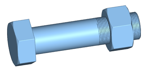
Example of 3D library parts.

|

|

|