2D Blocks
Objects created in 2D can be integrated into blocks. Blocks behave and are selected as single objects. The only time individual objects can be selected is when changing object color or line type. Connection points are used to define snap points for the block. A block is defined by:
- 2D objects, including nested blocks
- Insertion point
- Connection points (up to 32)
- Name and attributes
Blocks can be inserted into the current file, can be stored and inserted into other files.
There are libraries of mechanical parts (screws, bearings, threads, etc.) you can insert into your drawings. These are inserted as blocks, with predefined attributes. For more information, see Libraries of Mechanical Parts.
Creating and Inserting Blocks
Create Block - BLC |
To create a block, define the insertion point, any connection points, 2D objects that comprise the block, and block name and attributes. You can use one of the block attributes as the block name, and you can select whether the attribute will be blanked or unblanked. For visible attributes, the location of attribute text must be defined.
Save Block - BLS |
Saves the selected objects to a file. Enter the filename, define the insertion point, and select the block objects to be saved. It is recommended to select only one object.
Insert Block – BLI, Ctrl + K |
Inserts saved blocks into the drawing area. You can select blocks from a list of saved blocks. Select the location of the insertion point and you can drag the block to new locations. Insert Block is also invoked when you insert a part from a mechanical part library. This type of block is selected from an icon menu and created according to predefined dimensions.
During block insertion, you have the following additional insertion options:
Rotate or Scale - enables you to:
|
| New Insertion Point - changes the block insertion point. Insert the block first into a temporary position and then select the new insertion point. |
Editing Blocks
Edit Blocks - BLE |
If no block is open for editing and this function is invoked, you can select a block to edit. The selected block is highlighted and you can use any 2D functions to create, edit, or delete block objects.
If a block is currently open for editing and this function is invoked, the block objects are highlighted and inserted into a temporary work set. You can select other objects to add to the block, or select objects to be deleted from the block. See also Selecting 2D Objects.
Change Block Insertion Point - BIE |
Redefine the block insertion point.
Edit Block Attributes - BAE |
Add, edit or delete attributes of the selected block. The attributes list appears after you select the block. You can blank or unblank attributes as well, and for visible attributes you can change text position or text attributes as well.
2D Polylines
Objects created in 2D can be integrated into polylines, similarly as into blocks. Polylines also behave and are selected as single objects. Unlike blocks, you can integrate only existing lines, arcs or NURBS curves. Moreover, you can draw a new polyline instead integrating it.
Creating Polylines
Draw Polyline - CPL |
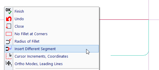
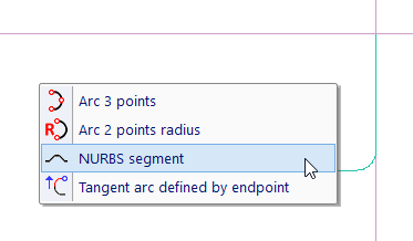
Drawing polyline, you can insert linear segments. Optionally (and by default), each corner is rounded. Also, you can insert a different type of segment. Icons containing polyline options are added into 2D input toolbar, or into pop-up (called by right + left click).

A pop-up containing polyline options. Drawing of polylines uses temporary and transient construction lines.

A pop-up containing options of different types of segments.
Join Objects into Polyline - PLL |
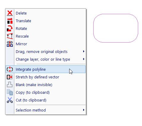
You can select existing objects and integrate them into polyline. If you select a set of objects and finish by right-click. If all selected objects can be integrated into polyline, the option is displayed in pop-up menu.

Selected objects, integration into polyline.
Editing Polylines
Polylines are edited the same way as blocks. Either select the command, or right-click a polyline and select editing from menu. See Editing Blocks. Unlike blocks, polylines do not have defined attributes or insertion point and connection points.