3D Objects Shape Representation
3D objects created in VariCAD are described as closed surfaces (closed shells). Objects loaded from STEP may be also open shells, or in case of detected error, surfaces originally closed - with some missing patches. Solids with missing patches, open shells or set of patches may be also created by conversions from other types – by VariCAD commands.
All types of objects can contain solid attributes, so they appear in BOM or other lists of parts. All types can be exported from 3D into 2D, as a part of 2D drawing. All types can be saved into STEP, IGES or STL. You can detect locations or measure distances or coordinates of points at all types. You can also define constraints among solids for any of these types.
On the other side, you can calculate volume, mass or moment of inertia (related to rotation axis) for only closed surfaces – for ordinary solids.
Types of Shape Representation

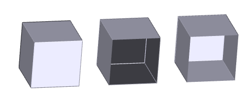
Example of a closed surface, missing patch and open shell
Closed Surfaces (Closed Shells)
Closed surface means that an object – solid is completely surrounded by patches. Each patch has outline created by 3D curves. Each such curve connects two adjacent patches. All operations available for 3D objects in VariCAD are supported.
Solids with Missing Patches
This type of object was originally created as a solid, described by closed surfaces. During STEP import, due to detected problems, one or several patches were deleted. Also, patches may be deleted in corresponding VariCAD command – see below.
Objects with missing patches support most of VariCAD 3D operations, except volume and moment of inertia calculations. Boolean operations and edges blending may be limited, though. These functions cannot work, if intersection curves created, for instance, by Boolean cut intersect an edge of a missing patch.
Solids with missing patches are displayed as “objects with holes”. Thru missing patch, you can see the solid from inside – patches are inside out there.
Open Shells
Open shells are also described similarly as closed surfaces by patches and 3D curves with two adjacent patches. However, open shells contain also curves surrounding only one patch.
Open shells do not support any volume or moment of inertia calculations, and do not support any Boolean operations or blending. If necessary, you can convert open shells to objects with missing patches and perform these operations at converted objects. Also, you can select one or more or all patches and create a shell with defined thickness, by offsetting of selected patches. See Offset Patches – Thick Shells.
Open shells are displayed as zero-thickness patches. The surface looks the same from both sides.
Set of Patches
Set of patches are described by set of single patches. Each patch is surrounded by its own outline. No neighboring patches are defined. This shape representation supports only basic operations (see above). If you convert a selected object into this representation, you cannot convert it back (except undo of editing command, if you do not leave VariCAD session).
If STEP contains shape representation by triangular facets (similar to STL data), VariCAD can load these triangles as a set of patches. However, such representation is only approximate. Different surface types than planes are replaced by certain number of planar facets. Moreover, this representation requires a lot of RAM.
Converting Shape Representations into Different Types
Although different shape representation than closed surfaces (solids) is used among objects loaded from STEP, you can also convert objects into other types by VariCAD commands.
There may be several reasons for such conversions:
- Objects must be saved into STEP for other software, which demands open shells or set of patches, but not closed solids.
- If you need to perform Boolean operation or blending at open shell, you can convert it into object with missing patches
For conversion, you can right-click an object and select a conversion type from a pop-up menu. However, this selection is not possible for the most standard type – for closed surfaces (solids).
Otherwise, use following commands:
Converts a Solid to Open Shell - OSHELL |
Select patches which will be removed during conversion. Also, you can optionally select patches which will create the open shell (as an opposite possibility of selection of patches).
Converts a Solid to Object with Missing Patches - PTCHM |
Selection of patches is similar as for creation of open shell
Converts a Solid to Set of Patches - PTCHS |
Selection of patches is also similar as for creation of open shell
For the commands above, selection of patches offers several options:
| Select All except Detected – all patches of entire solid are selected, except a patch which was clicked. This option may be convenient if you need to remove only one patch, or a few patches – others are selected in next steps. |
| Select One Side of Shell – click a shell, created in VariCAD as offset of patches. Entire surface is selected. Option may be used, for instance, if you need to export a shell with defined thickness into a system demanding only open shell with zero thickness. |
| Entire Solid from Sheet Metal – click a solid. If the solid is created as a sheet metal object, entire corresponding side (surface) is selected. |
| Selected Patches Are Saved – if checked, all selected patches are used for solid shape conversion. |
| Selected Patches Are Removed – if checked, all selected patches are removed before solid shape conversion. This is opposite possibility to the previous option. |
Highlighting Objects with Open Surfaces
As written above, some operations performed at open solids are limited or not supported. VariCAD provides possibilities to highlight such objects. You can also highlight boundaries of continuous patches of open shells or solids with missing patches. Consequently, you can easily see which objects from entire space do not support all features available for standard closed solids.
To display boundaries of solids with missing patches or boundaries of open shell, right-click an object and select the feature from menu. Also, open solids can be displayed in command 3D Space Information.
Following possibilities of open shells checking are available:
| Displays All Open Solids - DOS |
This command optionally highlights all open solids or all boundaries of continuous patches.
| Displays All Holes in Open Solid - DHOS |
Command displays boundaries of continuous patches of selected object. Boolean operations or blendings are not supported, if intersections calculated during operation further intersect these boundaries.
| Displays All Holes in Open Solid Around Deleted Patches - DHEOS |
Command displays boundaries of continuous patches of selected object, similarly as the previous command. However, only boundaries of deleted patches are highlighted. Deleted patches are removed during input of STEP files, if an error is detected and the patch cannot be processed. This command is useful as detection of incompletely loaded objects from STEP.

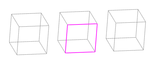
Example of highlighted boundaries of an open solid, here a solid with missing patch